20
────────────────────────────────────────────────────
2.5 Logic Probe Connection
────────────────────────────────────────────────────
DANGER
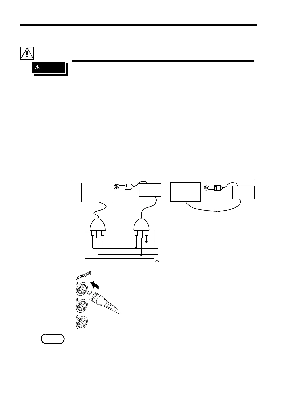
The logic input and 8841/42 Unit share a common ground. Therefore, if
power is supplied to the measurement object of the logic probe and to
the 8841/42 from different sources, an electric shock or damage to the
equipment may result.
Even if power is supplied from the same system, if the wiring is such
that a potential difference is present between the grounds, current will
flow through the logic probe so that the measurement object and
8841/42 could be damaged. We therefore recommend the following
connection method to avoid this kind of result.
(1) Before connecting the logic probe to the measurement object, be
sure that power is supplied from the same outlet box to the
measurement object and the 8841/42 using the supplied power
cord.
(2) Before connecting the logic probe to the measurement object,
connect the ground of the measurement object to the 8841/42
ground terminal. Also in this case, power should be supplied from
the same source. Refer to Section 2.2, "Power Supply and Ground
Connections" for grounding terminal details.
Object to be
measured
8841/42
Outlet
Power su
l
Ground
Figure 1
8841/42
Function
round terminal
GND
Figure 2
Object to be
measured
In this case too, obtain power
from the same supply.
NOTE
2.5 Logic Probe Connection
・The logic input is located on the rear of the unit. Up
to four probes can be connected.
・Since one logic probe can record 4 channels, the
combined maximum recording capability for logic
waveforms is 16 channels.
・Connect the probe by aligning the groove on the plug
with the ridge on the connector.
・ If no logic probe is connected, the corresponding logic waveform is
displayed on the screen at high level.
・ Carefully read the instruction manual supplied with the probe.
・ Do not connect logic probes other than supplied by HIOKI to the logic
inputs.