235
────────────────────────────────────────────────────
10.8 Analog Trigger
────────────────────────────────────────────────────
Signal cycle
Lower limit 1
Lower limit 2
Reference
voltage
Signal cycle
Reference
voltage
Example of upper limit 1
Example of upper limit 2
0.95 s 1.05 s
1.10 s
1.20 s
Reference voltage
0.000 V
Within the
period range
Within the
period range
Upper limit of
the period
Triggering position of the period trigger
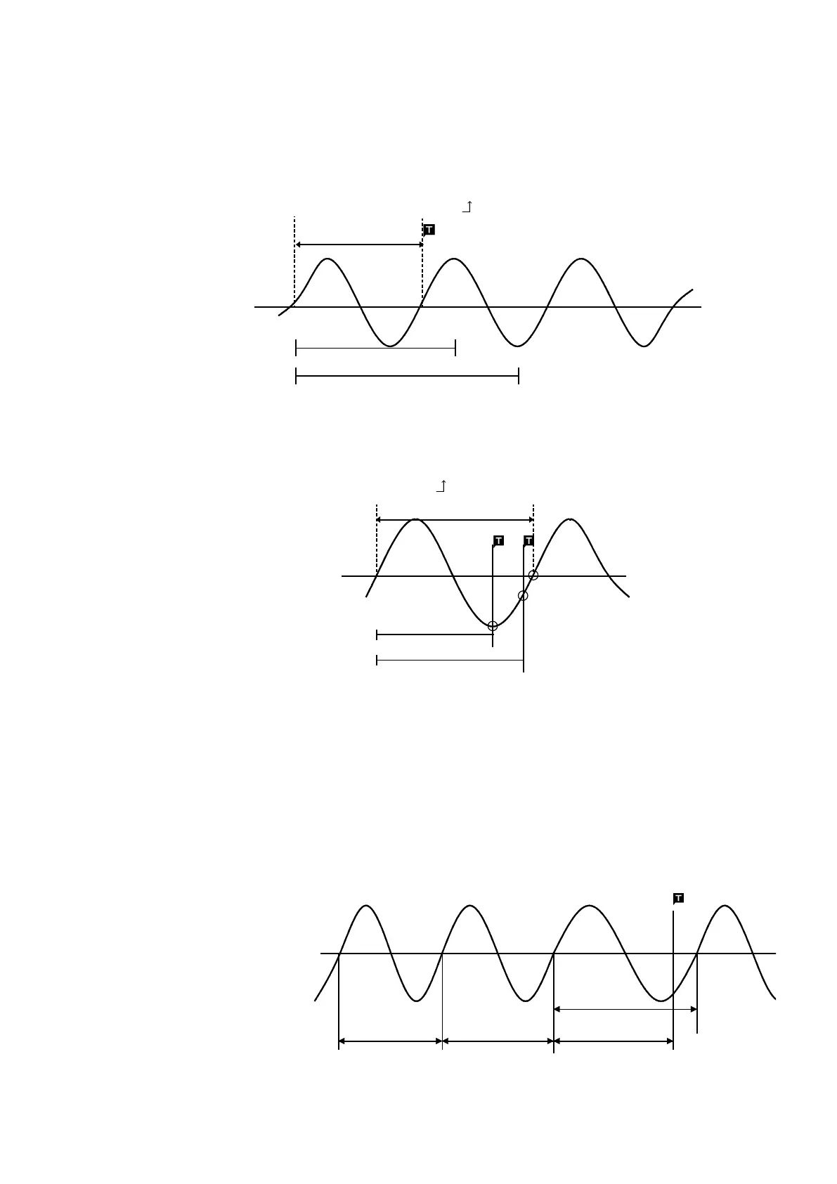
The system monitors the period of the signal that crosses the set reference
voltage. When the monitored period deviates from the set range, triggering
occurs. The trigger position is determined by the set period range and the
measurement signal period.
Signal with a period to be measured that is smaller than the lower limit of
the period trigger (trigger slope:
):
When the signal crosses the reference voltage at the set trigger slope before
the lower limit of the set period range appears on the screen, the intersection
is always defined as the triggering position.
Signal with a period to be measured that is larger than the upper limit of the
period trigger (trigger slope:
):
When the upper limit of the set period range appears on the screen before
the signal crosses the reference voltage at the set trigger slope, the upper
limit is defined as the triggering position. The triggering position is
determined by the position of the upper limit in the period range, as shown
in the figure above.
Example for Period Trigger
In order to cause triggering when the signal as shown in the figure below
leaves the period range of 0.9 to 1.1 s, the following settings are made:
Lower limit of the period: 900 ms, Upper limit of the period: 1.1 s,
Reference voltage : 0.000 V