214
────────────────────────────────────────────────────
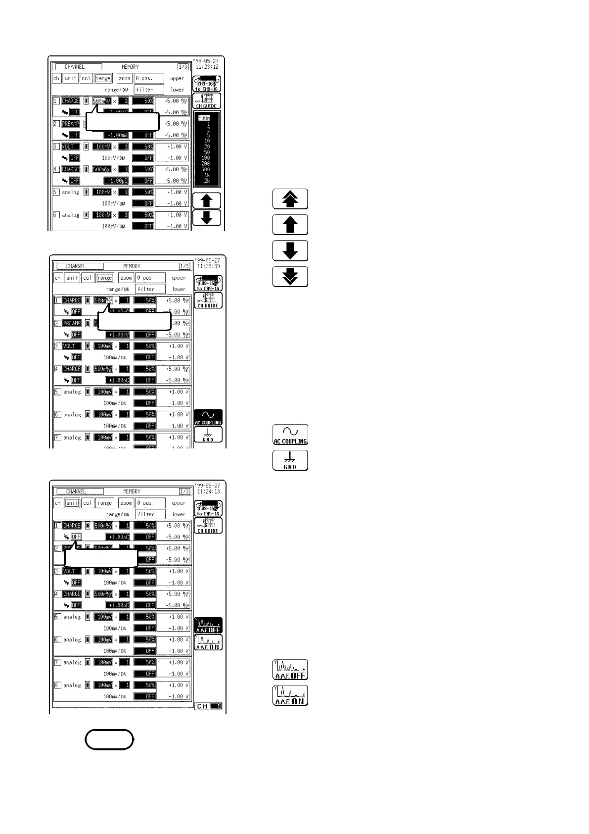
9.15 Setting the 8947 CHARGE UNIT
────────────────────────────────────────────────────
Flashing cursor
Flashing cursor
Flashing cursor
Function
display
Meaning
:
Increases in number, large step
:
Increases in number, small step
:
Decreases in number, small step
:
Decreases in number, large step
Function
display
Meaning
:
AC coupling
:
The input signal is not connected. This allows
the zero position to be checked.
Function
display
Meaning
:
Anti-aliasing filter is not used.
:
Anti-aliasing filter is used.
NOTE
(3) Set the measurement range
The measurement range varies according to sensor
sensitivity. Set the sensor sensitivity before you set the
measurement range.
1. Move the flashing cursor to the position shown in the
figure on the left.
2. Use the function keys to set the measurement range.
(4) Set the input coupling
DC coupling is not available in the Charge and Preamp
modes.
1. Move the flashing cursor to the position shown in the
figure on the left.
2. Use the function keys to set the input coupling.
(5) Set the anti-aliasing filter
Enable the anti-aliasing filter to prevent aliasing
distortion. The cut-off frequency changes automatically
when setting the frequency and time axis ranges. The
anti-aliasing filter can only be selected from the
CHANNEL screen.
1. Move the flashing cursor to the position shown in the
figure on the left.
2. Use the function keys to make a setting.
Refer to Section 8.3.3, "Setting the Frequency Range" for details about the
relationship between the anti-aliasing filter cutoff frequency and the
frequency range and time axis range.
 Loading...


