219
────────────────────────────────────────────────────
10.2 Operation Sequence (Trigger mode setting)
────────────────────────────────────────────────────
1
2
3
4
5
6
7
8
9
10
11
12
13
14
A
Selecting trigger type
・ The analog signal input channels can be used as trigger source.
・ The type of trigger that can be used for the various functions is limited.
Analog trigger
Trigger level
Input
aveform
Tri
er slo
e
Upper limit
Lower limit
Upper limit
Lower limit
1/2period
Upper limit
Lower limit
Tri
er slo
e
Trigger level
Input
aveform
Reference voltage:
0.000 V
Period lower
limit: 900 ms
Upper limit
1.1 s
Within
eriod ran
e
U
er limit
0.95 s 1.05 s 1.10 s
1.20 s
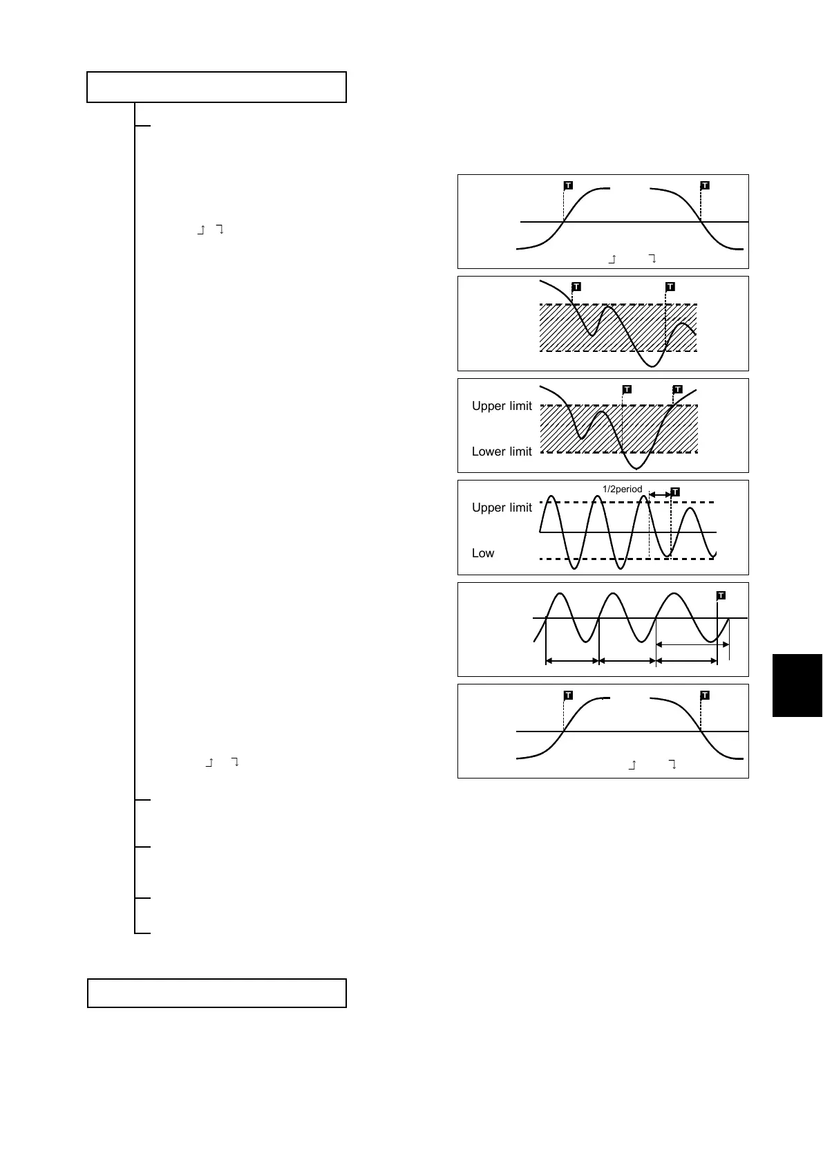
Level trigger (MEM, REC, REC&MEM, FFT)
Triggering occurs when the input signal crosses the
preset trigger level (voltage) with the preset trigger
slope (
, ).
Window-in Trigger (MEM, REC, REC&MEM, FFT)
Set upper limit level and lower limit level and
activated when the input signal enters the range
between these limits.
Window-out Trigger (MEM, REC, REC&MEM, FFT)
Set upper limit level and lower limit level and
activated when the input signal leaves this range.
Voltage drop Trigger (MEM, REC, REC&MEM, FFT)
This unit designed to measure commercial power
supplies (50/60 Hz). This unit detects momentary
voltage drops in commercial power supplies. When
the peak of the voltage falls lower than the setting
level, the trigger will occur.
Period Trigger (MEM, REC, REC&MEM, FFT)
This function sets both the period reference voltage
and the period range, and measures the rise (fall)
period of the set voltage. When the measured
period deviates from the specified range, triggering
occurs.
RMS level Trigger (rms value)
The commercial power supplies, 50/60 Hz and the
DC signals can be measured.This trigger occurs
when the input signal crosses a predetermined
trigger level (rms value) in a particular direction
("slope":
or ).
Logic trigger
The signal of a logic channel can be used as trigger source. A trigger pattern and
logical operator (AND/OR) are specified, and triggering occurs when the trigger
conditions are met.
External Trigger
An external signal can be used as trigger source. The external trigger is activated
by either shorting the EXT TRIG terminal or applying a falling edge signal going
below 2.5 V.
Timer Trigger
This function serves to activate recording at preset times. Triggering can be
performed at constant intervals within a preset start time and end time.
Manual Trigger
The manual trigger is always activated when the
MANU TRIG
key is pressed,
regardless of trigger source AND/OR linking setting.
Start measurement
・ Press the
START
key and the LED lights. When the trigger conditions are met,
measurement start.
・ Pressing the
STOP
key stops measurement.