230
────────────────────────────────────────────────────
10.8 Analog Trigger
────────────────────────────────────────────────────
s882-2,3
Function
display
Meaning
:
Trigger filter is disabled.
:
Trigger filter is enabled.
Filterwidthis10ms.
1.
3.
2.
4.
5.
6.
Setting items
Operation
Function Jog/Shuttle
1.
Trigger mode
2.
Trigger type
3.
Channel
4.
Upper limit
5.
Lower limit
6.
Pre-trigger
●
●
●
●
●
●
−
−
●
●
●
●
1V
-1 V
0V
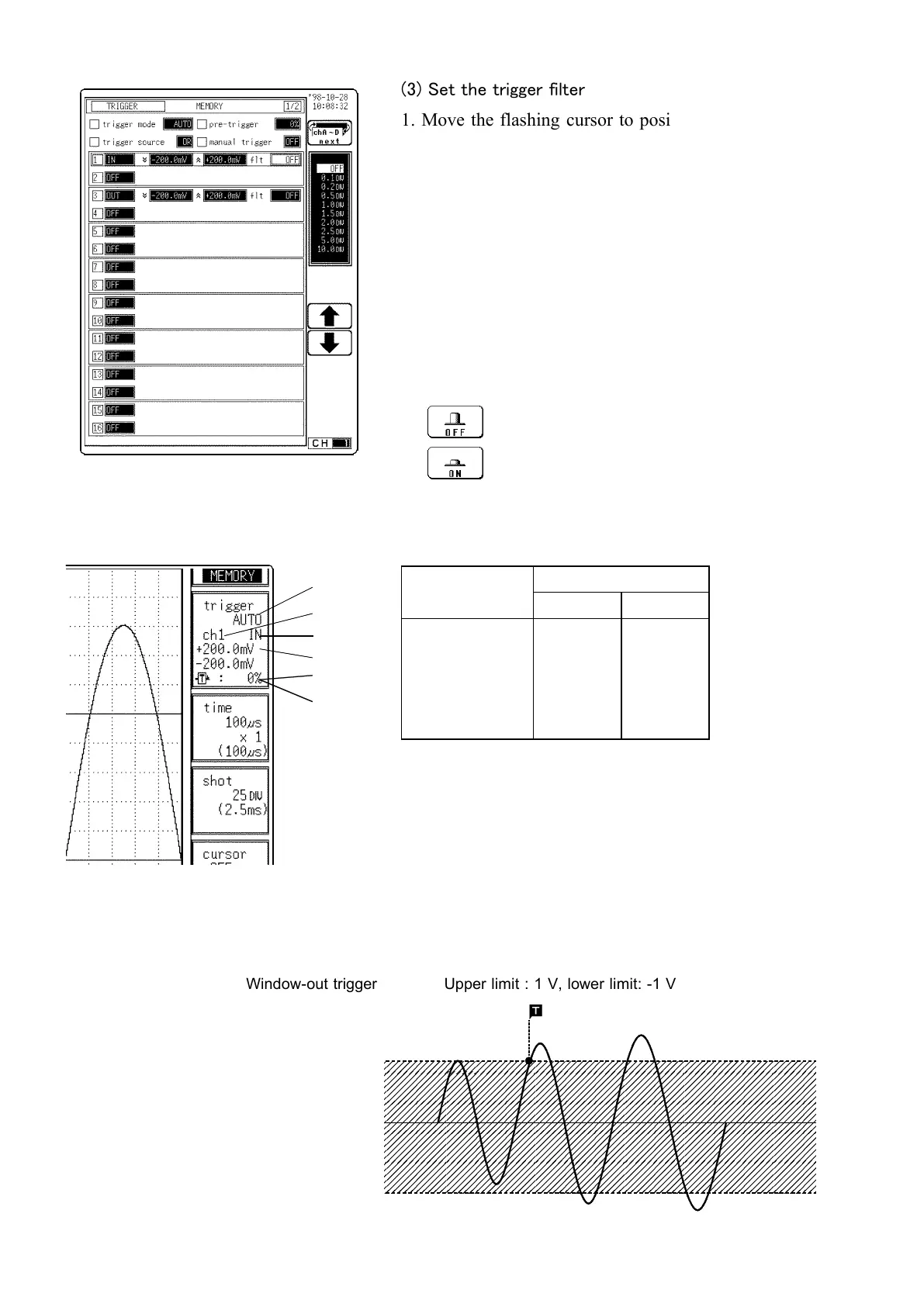
Window-out trigger Upper limit : 1 V, lower limit: -1 V
(3) Set the trigger filter
1. Move the flashing cursor to position shown in the
figure on the left.
2. Use the Jog/Shuttle control or the function keys to
make the selection.
In the Memory recorder, Recorder& Memory, FFT
Functions
OFF
Trigger filter is disabled
0.1
to
10
Trigger filter is enabled. Filter width is
specified using divisions.
In the Recorder Function
Settings on the Waveform display screen
Restriction: The trigger filter cannot be set.
To set the numerical value by using the Jog/Shuttle
control, press the VALUE key.
The selected window is not displayed in the pre-trigger
setting.
Example for Window-out Trigger
In order to cause triggering when the signal as shown in the figure below
leaves the hatched area, the following settings are made:
 Loading...


