297
────────────────────────────────────────────────────
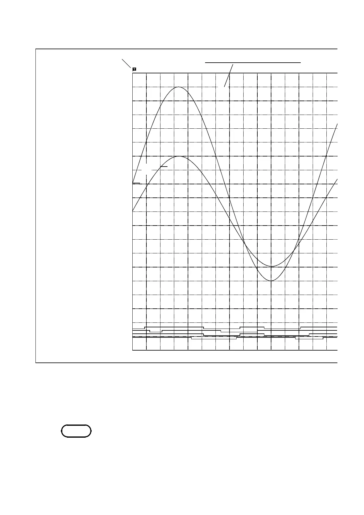
13.5 Example of Printer Output
────────────────────────────────────────────────────
'98 - 02 - 20 - 0017
HIOKI 8841 MEMORY HiCORDER
Upper
1:
7V
2:
4V
Lower
1:
-7 V
2:
-4 V
ch1COMMENT
ch2 COMMENT
4.
2.
3.
1.
1.
6.
chA2 COMMENT
chA3 COMMENT
chA4 COMMENT
5.
CH
CH
ch2 COMMENT
ch1 COMMENT
NOTE
Advanced settings
1. Upper-lower print(ON)(See Section 13.4.1)
2. 0 position comment(ON)(See Section 13.4.1)
3. Counter print(DATE)(See Section 13.4.1)
4. Title(COMMENT)(See Section 9.9)
5. Logic(COMMENT)(See Section 9.9)
6. Channel marker(COMMENT)(See Section 13.4.1)
・ The gauge, upper and lower limits, and 0 position comments are printed out
in this order. Since the 0 position and logic channel comments are printed
out in the same space, the positions must be specified so that these
comments will not overlap each other.
・ If 0 position comments are printed on channels having the same 0 position,
the printed comments will overlap each other.