18
────────────────────────────────────────────────────
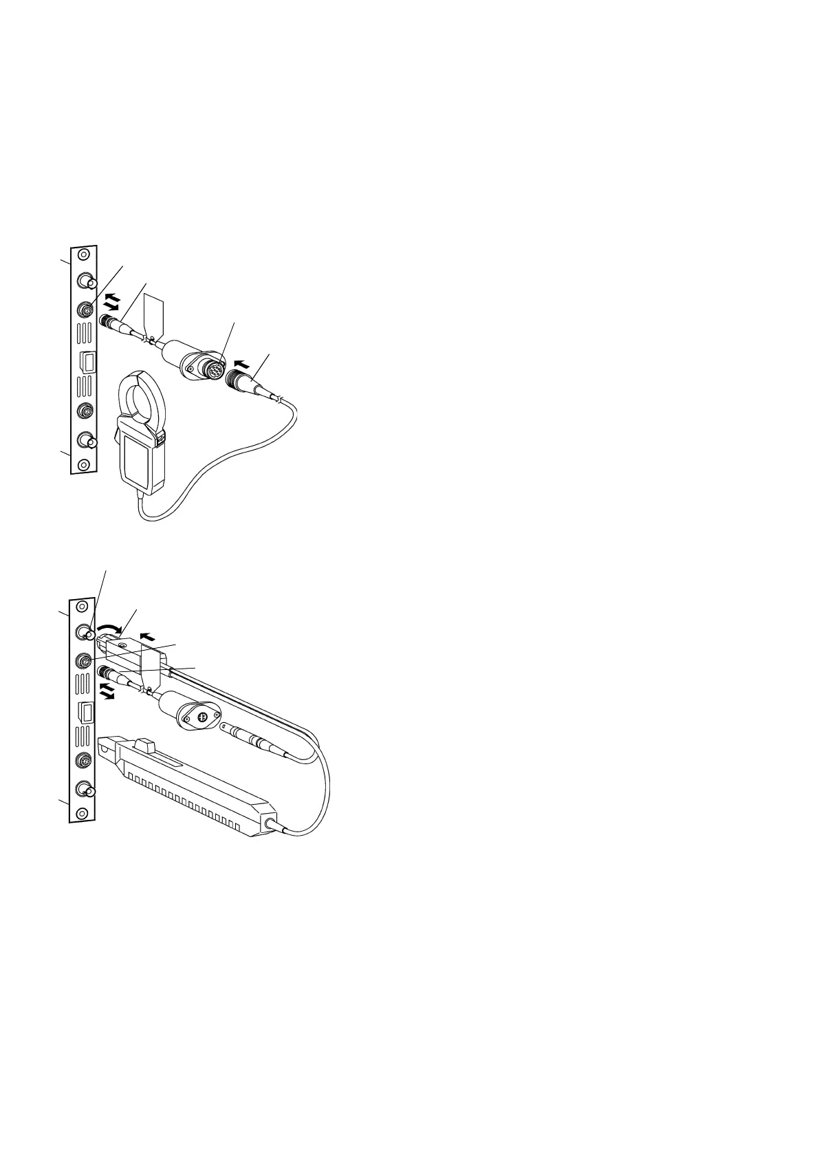
2.4 Connection of the Input Unit
────────────────────────────────────────────────────
Adapted clamp's
plug
Unit's sensor connector
Conversion cable plug
Conversion cable connector
Groove on the 3273 CLAMP ON
PROBE's termination connector
Conversion cable plug
Pro
ection on the unit connector
Sensor connector
on the unit
Clamp connection (Current measurement)
The following clamp-on sensors and clamp-on probes can be connected
using the 9318 and 9319 CONVERSION CORDs.
9318
:9270, 9271, 9272, 9277, 9278, 9279
9319
:3273
It can be connected to a maximum of 4 channels.
Connecting the 9318 CONVERSION CABLE
1. Align the groove on the conversion cable plug with
the sensor connector on the F/V unit and push
inward until the connector locks into place.
2. Align the groove on the conversion cable connector
with the adapted clamp on sensor plug and push
inward until the connector locks into place.
3. To unplug the cables, slide the lock ring on each
plug outward to unlock it, then pull out the plug.
Connecting the 9319 CONVERSION CABLE
1. Align the groove on the 3273 CLAMP ON
PROBE's termination connector with the pin on the
BNC connector on the F/V unit, then slide the
termination connector over the BNC connector and
turn to lock it in place.
2. Align the groove on the conversion cable plug with
the sensor connector on the F/V unit and push
inward until the connector locks into place.
3. Unlock the conversion cable connector and the
power plug on the 3273 before unplugging the
cable.
4. To unplug the cables, slide the lock ring on each
plug outward to unlock it, then pull out the plug.