417
────────────────────────────────────────────────────
20.2 Replacing the Input Units
────────────────────────────────────────────────────
16
17
18
19
20
6
7
8
9
10
11
12
13
14
A
WARNING
To avoid the danger of electric shock, never operate the
product with an input module removed. To use the product
after removing an input module, install a blank panel over
the opening of the removed module.
The mounting screws must be firmly tightened or the input
module may not perform to specifications, or may even fail.
To avoid the danger of electric shock, never operate the
product with an input module removed. To use the product
after removing an input module, install a blank panel over
the opening of the removed module.
When replacing the 8936
Handle
NOTE
20.2 Replacing the Input Units
・ The following procedure describes how to remove the input unit.
・ Install the units by reversing the procedure for removal.
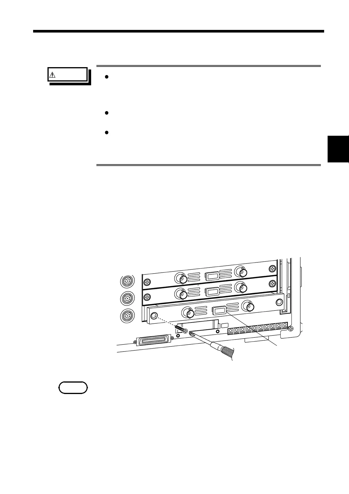
1. Remove the connector cables from all input units.
2. Power off the 8841/42 main unit, and disconnect the power cord.
3. Remove the two fixing screws with a Phillips screwdriver, as shown in the
figure below.
4. To remove the input unit, grasp handle or BNC connector.
Do not measure with a blank panel removed. Otherwise, the unit internal
temperature becomes unstable and consequently the specifications are not
met.