4: Sourcing and measuring 2470 High Voltage SourceMeter Instrument
4-4 2470-901-01 Rev. A / May 2019
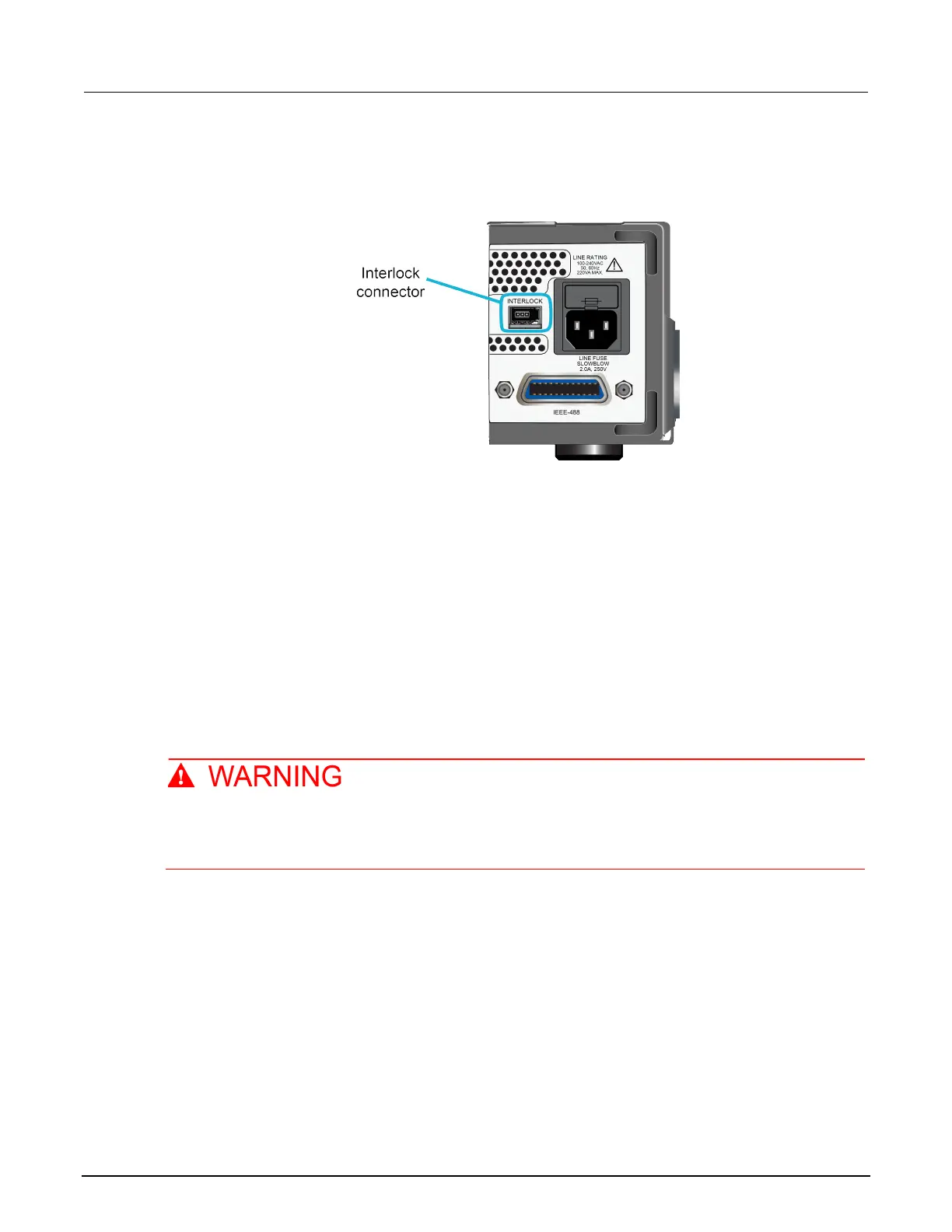
Location of the interlock connection
Figure 54: Rear-panel interlock location
Interlock connector pins
An interlock circuit is provided on the rear panel of the instrument. This circuit must be closed to
enable the 2470 to produce voltages greater than ±42 VDC.
The interlock is intended for use through a normally open switch, which may be installed on the lid of
a test fixture, on the enclosure of a semiconductor prober or device handler, or on the door or doors
of a test equipment rack. The circuit opens when an access door is opened, and closes when the
door is closed.
When the interlock is asserted, the FORCE and GUARD terminals should be considered hazardous
voltages, even if they are programmed to a non-hazardous voltage or current.
Potentially hazardous voltages of up to approximately 1350 V may be present at the High
Force, High Sense, and Guard terminals when the interlock circuit is closed.
To prevent electrical shock, do not expose these lines.
You can use the Keithley Instruments connector CS-1616-3 Safety Interlock Mating Connector,
supplied with the 2470, to make the interlock connection to the rear panel. You must supply
connection wire. The recommended wire is:
• 20 AWG to 24 AWG copper alloy
• 7 to 19 bare and tinned strands
• 0.25 mm
2
to 0.50 mm
2
• Flexible vinyl, semi-flexible vinyl, polyethylene, x-linked polyethylene, or PTFE
 Loading...


