High Voltage SourceMeter Instrument Reference Manual Section 5: Source-
2470-901-01 Rev. A / May 2019 5-5
When the instrument is operating in quadrant II or IV, the instrument is operating as a sink, which
means that voltage and current have opposite polarity. As a sink, the instrument dissipates the power
internally. An external source or an energy storage device, such as a battery, solar cell, or power
supply, can force operation in the sink region. The ability of the instrument to dissipate power is
defined by the boundaries shown in the following figures.
Current source operating boundaries
The operating boundaries for the current source are determined by the source range and limit settings.
The operating boundary is the lower of the two settings. For example, if the 100 mA current source
range is selected, the current source is limited to 105 mA, even if the source limit is set to 1 A.
The voltage limit line represents the actual limit that is in effect. These limit lines are boundaries that
represent the operating limits of the instrument for this quadrant of operation.
The operating point can be anywhere in or on these limit lines. The figure below shows operating
boundaries for the current source for quadrant I. Operation in the other three quadrants is similar.
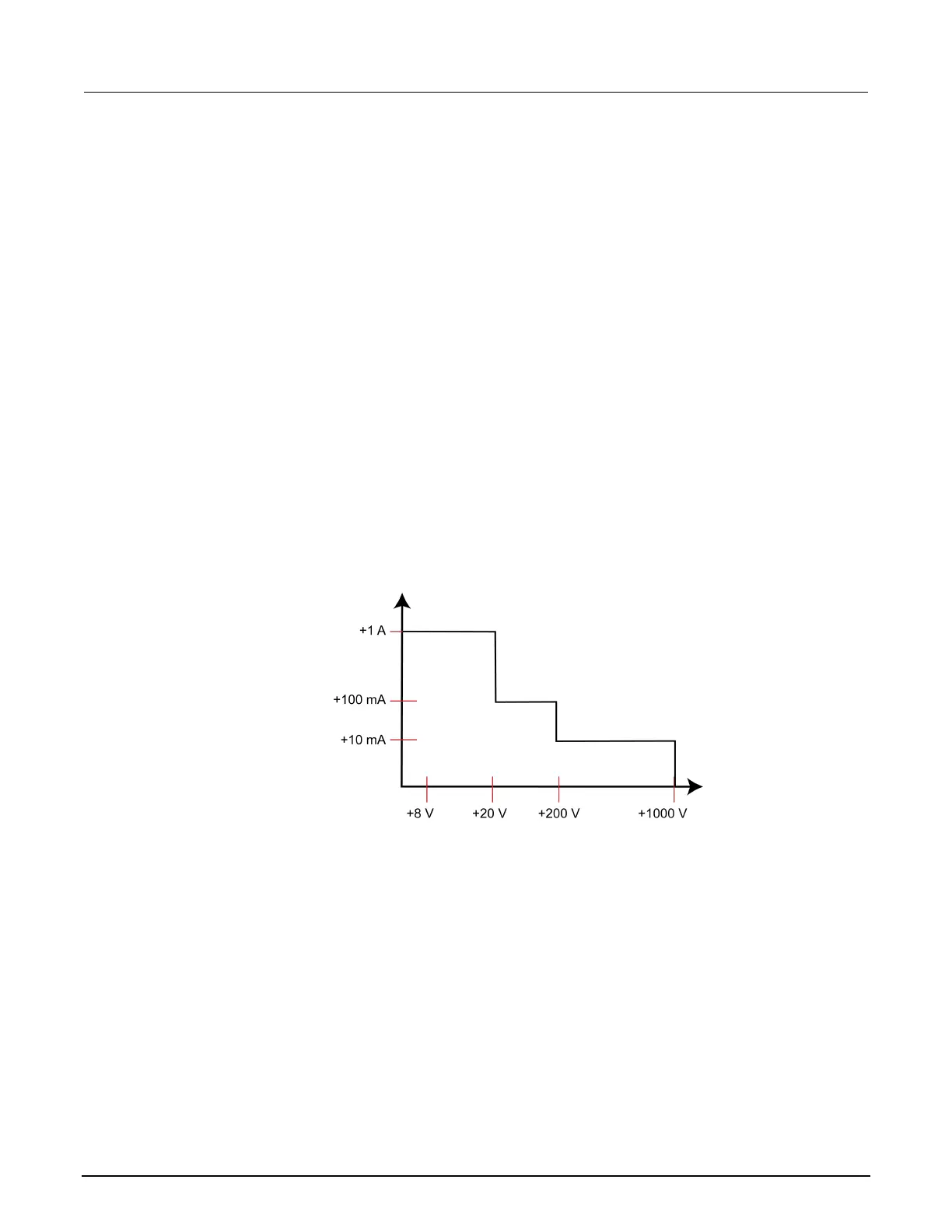
The current source line is the maximum source value possible for the presently selected current
source range.
Figure 91: 2470 current source output characteristics
Voltage limit boundary examples
The actual boundaries where the instrument operates depends on the device under test (DUT) that is
connected to the output of the instrument.
The following graphs show operation with the instrument set to source 100 mA with a limit of 40 V. In
this graph, the resistive load is 200 Ω. The instrument is sourcing 100 mA to the 200 Ω load and
subsequently measures 20 V. The load for 200 Ω intersects the 100 mA current source at 20 V.

 Loading...


