High Voltage SourceMeter Instrument Reference Manual Section 12:
2470-901-01 Rev. A / May 2019 12-175
Details
The digital trigger pulsewidth command determines how long the trigger is asserted.
The trigger stimulus for a digital I/O line can be set to one of the trigger events that are described in
the following table.
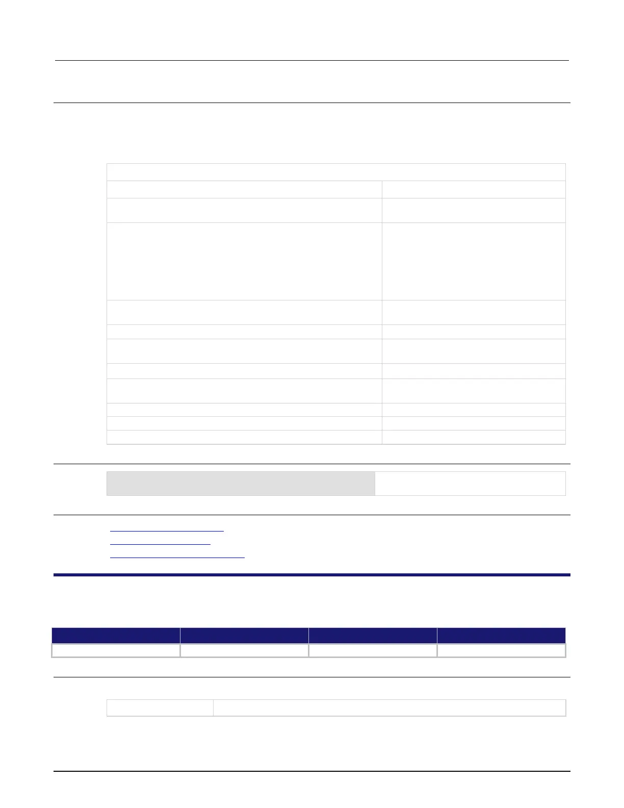
Trigger events
Event description Event constant
Trigger event blender <n> (up to two), which combines trigger
events
A command interface trigger:
Any remote interface: *TRG
GPIB only: GET bus command
USB only: A USBTMC TRIGGER message
VXI-11: VXI-11 command
Line edge (either rising, falling, or either based on the
configuration of the line) detected on digital input line
(1 to 6)
Front-panel TRIGGER key press
Appropriate LXI trigger packet is received on LAN trigger object
<n> (1 to 8)
Notify trigger block <n> (1 to 8); the trigger model generates a
trigger event when it executes the notify block
Source limit condition occurs
Trigger timer <n> (1 to 4) expired
Line edge detected on TSP-Link synchronization line
(1 to 3)
Example
:TRIG:DIG2:OUT:STIMulus TIM3
Set the stimulus for output digital trigger line
2 to be the expiration of trigger timer 3.
Also see
Digital I/O port configuration (on page 8-13)
:DIGital:LINE<n>:STATe (on page 12-26)
:TRIGger:DIGital<n>:OUT:LOGic (on page 12-173)
:TRIGger:LAN<n>:IN:CLEar
This command clears the event detector for a LAN trigger.
Type Affected by Where saved Default value
Usage
:TRIGger:LAN<n>:IN:CLEar
The LAN event number (1 to 8) to clear

 Loading...


