High Voltage SourceMeter Instrument Reference Manual Section 8:
2470-901-01 Rev. A / May 2019 8-13
Digital I/O connector and pinouts
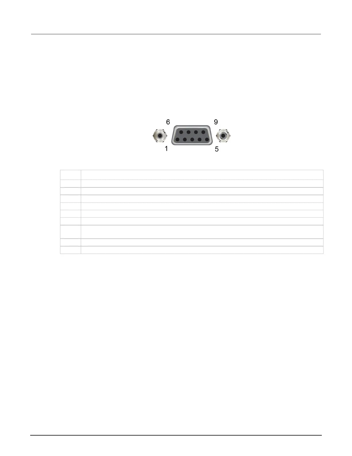
The digital I/O port uses a standard female DB-9 connector, located on the rear panel of the 2470.
You can connect to the 2470 digital I/O using a standard male DB-9 connector. The port provides a
connection point to each of the six digital I/O lines and other connections, as shown in the following
table.
Figure 126: 2470 digital I/O port
2470 digital I/O port pinouts
Pin Description
V
ext
line (relay flyback diode protection; maximum 33 V)
+5 V line. Use this pin to drive external logic circuitry. Maximum current output is 500 mA. This line is
protected by a self-resetting fuse (one-hour recovery time).
Digital I/O port configuration
The following figure shows the basic configuration of the digital I/O port.
To set a line high (nominally +5 V), write a 1 to it; to set a line low (nominally 0 V), write a 0 to it. To
allow an external device to control the state of the line, the line must be set to input mode or
open-drain mode. An attached device must be able to sink at least 50 µA from each I/O line.

 Loading...


