228
────────────────────────────────────────────────────
10.8 Analog Trigger
────────────────────────────────────────────────────
1.
3.
2.
4.
5.
6.
Setting items
Operation
Function Jog/Shuttle
1. Trigger mode
2. Trigger type
3. Channel
4. Trigger level
5. Trigger slope
6. Pre-trigger
●
●
●
●
●
●
−
−
●
●
−
●
0V
-600 mV
B
200 mV
0V
2.
1.
Settings on the Waveform display screen
Restriction:
The trigger filter cannot be set.
The selected window is not displayed in the pre-trigger
setting.
To set the numerical value by using the Jog/Shuttle
control, press the
VALUE
key.
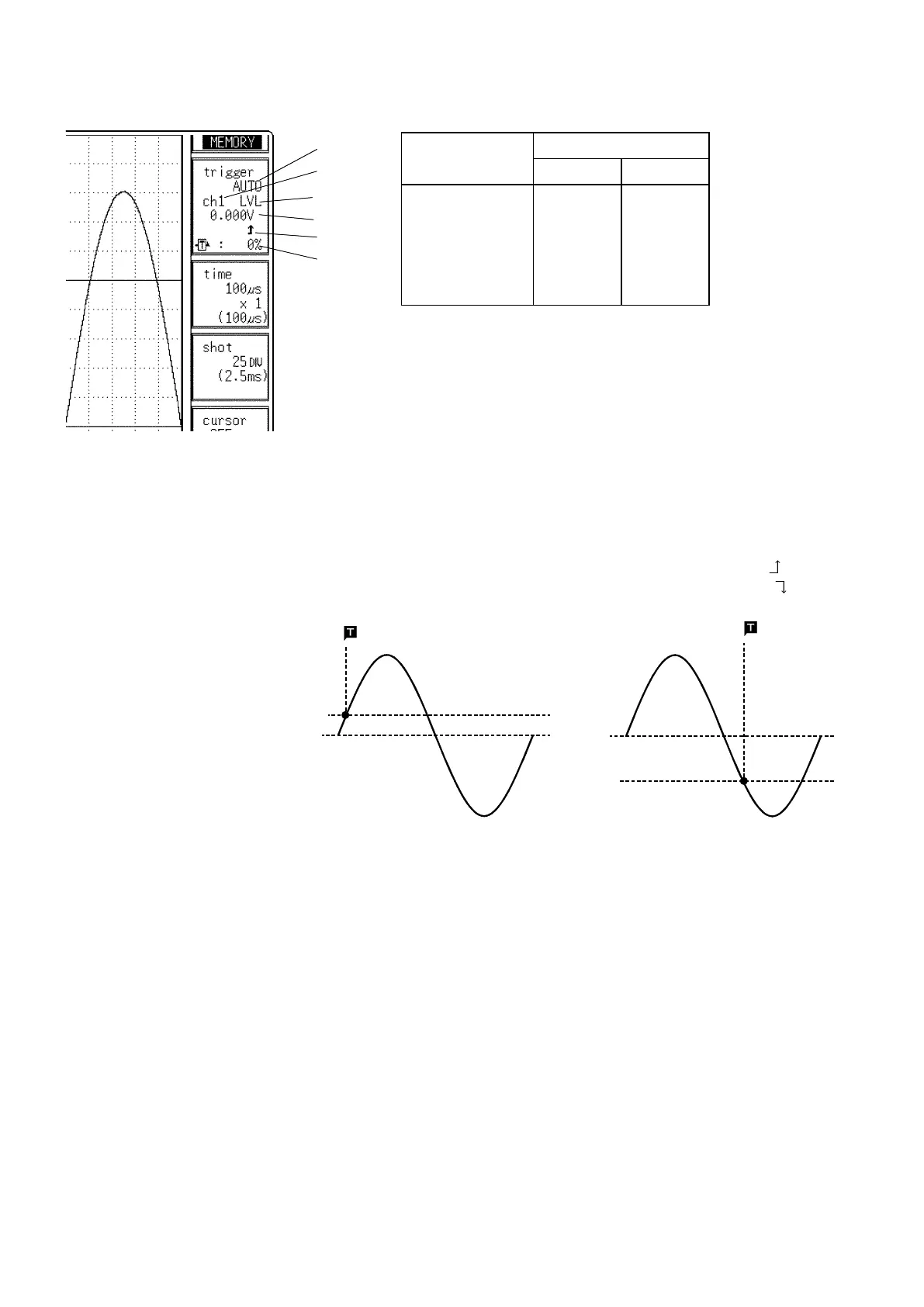
Example for Level Trigger
To cause triggering at point A or point B with the sine wave shown below,
make the following settings.
1.
Point A trigger level: 200 mV, trigger direction (slope): rising ( )
2.
Point B trigger level: -600 mV, trigger direction (slope): falling ( )
When the trigger source is set to "AND," triggering occurs when the voltage
is above or below the trigger level. With this setting, triggering will not
occur when the trigger slope crosses the set trigger level.