5
────────────────────────────────────────────────────
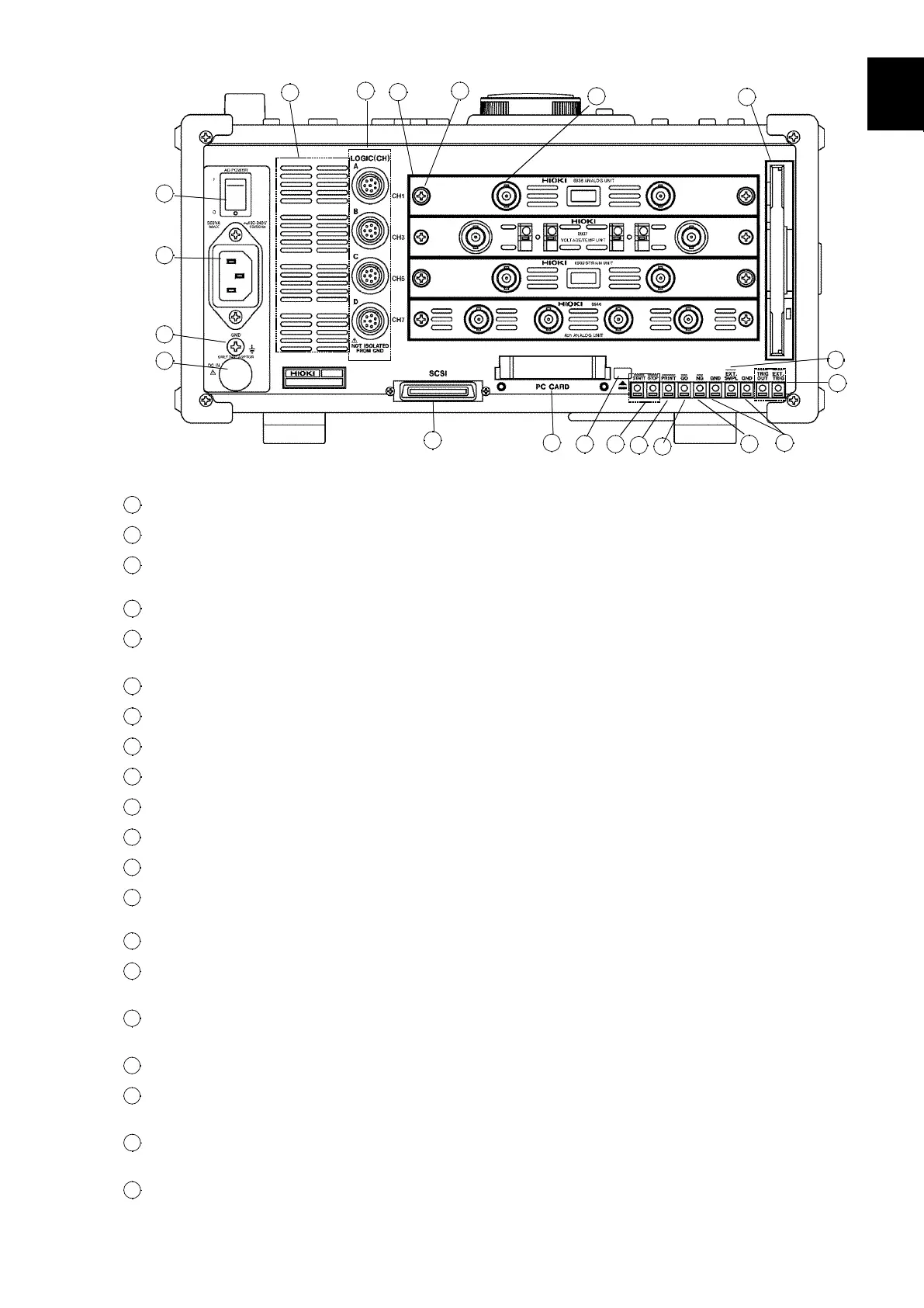
1.2 Identification of Controls and Indicators
────────────────────────────────────────────────────
1
2
3
4
5
6
7
8
9
10
11
12
13
14
A
1
2
10
3
4
5
6
7
8
9
11
12 13
14
15
16
17
18
19
20
Ri
ht Side Panel
1
AC power switch
Switches on or off the AC power supply.
2
AC connector
The supplied power cord must be plugged in here.
3
Function ground terminal
(GND)
Connects to the earth.
4
DC connector
Connects to the optional 9433 DC POWER ADAPTER.
5
Logic probe connectors
Input connector for the logic input section, designed for the
dedicate logic probes (CH A to D).
6
Input unit slots
These slots accept input units.
7
Fastening screw
Secures the plug-in unit.
8
Analog input connector
Unbalanced analog input. (on ANALOG UNIT)
9
FD slot
Floppy disk is inserted.
10
SCSI connector
An MO drive can be connected.
11
PC card slot
Inserts the PC card.
12
Eject button
Removes the PC card.
13
External start/stop
terminals
Start and stop operation can be controlled.
14
External print terminal
Print operation can be controlled.
15
GO evaluation output
terminal
When the waveform evaluation has resulted in GO, a signal is
output from this terminal.
16
NG evaluation output
terminal
When the waveform evaluation has resulted in NG, a signal is
output from this terminal.
17
Ground terminal (GND)
Uses with
⑬
to
⑲
(except
⑰
)terminals.
18
External sampling terminal
Allows input of an external sampling signal. (in Memory recorder
and FFT functions)
19
Trigger terminals
Can be used to synchronize multiple units, using the EXT TRIG
input and TRIG OUT output.
20
Blowing slot