Engine
SHOP MANUAL
Ch 1 page 55
Work description:
1. Make sure that the inlet pipe
between the
turbocharger and the air
cleaner has been
removed.
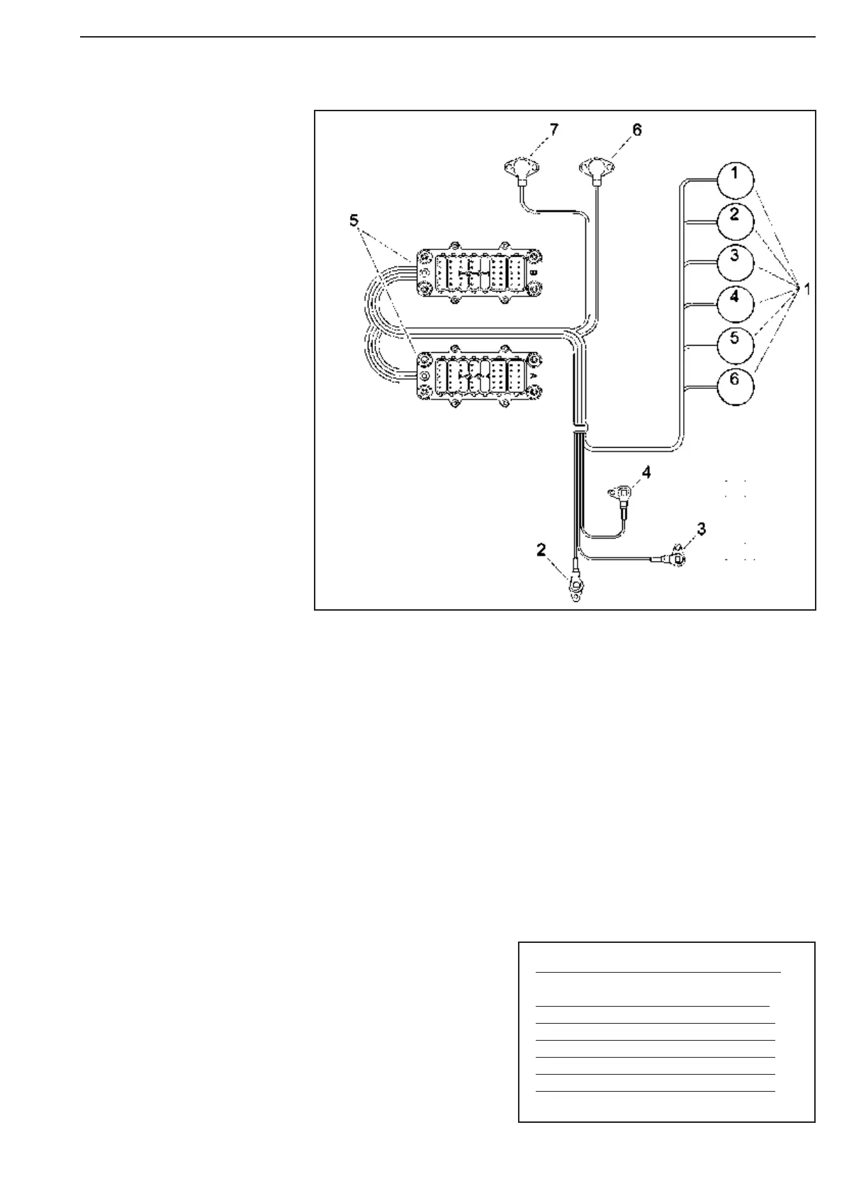
2. Fit the cable ducts. Sche-
matic illustrations
of the location of the cable
ducts and their
components are shown below
1 Cylinder 1–6
2 Coolant temperature sensor
3 Engine speed sensor 1 on flywheel
4 Engine speed sensor 2 on flywheel
5 Connector to control unit
6 Charge air pressure and temperature sensor
7 Oil pressure sensor
3
Run the cables to the unit injectors.
Check that you have run the right cable to
each unit injector by testing the cables with
a multimeter as shown in the tables.
Cylinder Connector Pin
1 B2 1 and 6
2 B2 2 and 7
3 B2 4 and 9
4 A1 1 and 6
5 A1 2 and 7
6 A1 4 and 9
Figure 87
Figure 88