Ch 6 page 69
ELECTRICAL SYSTEM
SHOP MANUAL
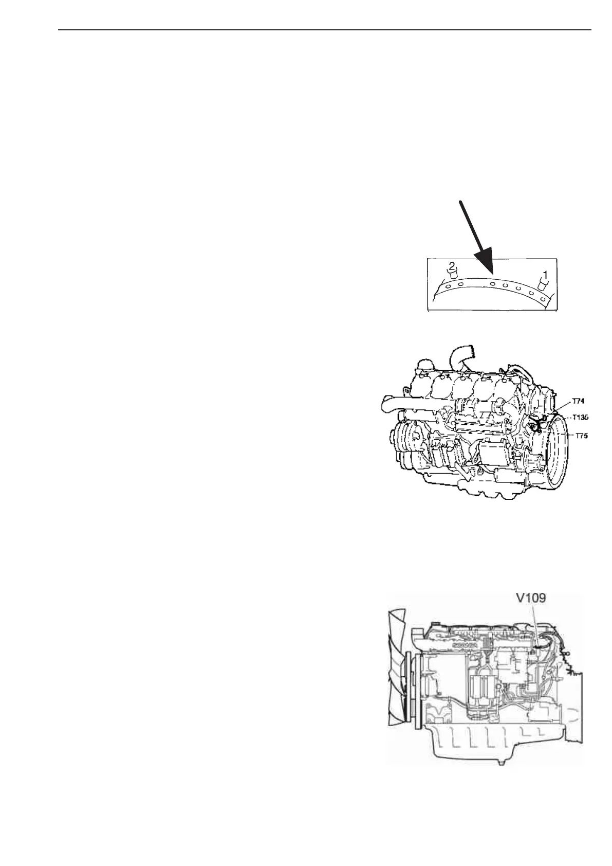
Engine speed sensors
1 Engine speed sensor 1, T74
2 Engine speed sensor 2, T75
The detail shows some of the holes in
the flywheel that are detected by the
engine speed sensors.
There are two engine speed sensors in the EMS system, en-
gine speed sensor 1 and engine speed sensor 2. The sensors
are inductive. This means that they only produce signals when
the engine is running.
The signal strength varies significantly, depending on the air
gap between the sensors and the flywheel as well as on the
engine speed.
The EMS system performs an assessment of the signal
strength at different engine speeds.
If the signal strength becomes too low, a fault code is gener-
ated.
Both engine speed sensor 1 and engine speed sensor 2 read
the position of the flywheel.
This means that the system cannot determine which of two
possible revolutions the engine is at, i.e.
whether, for example, cylinder 1 or cylinder 6 is at the ignition
position.
Every time the engine is stopped and the voltage cut off, the
engine position is stored.
Next time the voltage is switched on, the stored position of the
engine is used to determine which
revolution the engine is at.
When the engine has started, a system check is performed to
verify that the stored position is correct.
Resistance: 485-595 W
Inductance: 187-253 mH
Measure between: 541- 1 and 2
Distance between sensor and
flywheel/gear ring: 0,5- 1,5mm
Engine speed and camsghaft sensors
The solenoid valve for the wastegate
valve receives signals from the
engine control unit and regulates the
turbocharger charge pressure via the
wastegate valve.
Wastergate solenoid valve
Figure 50
Figure 49
Figure 51