SHOP MANUAL
DRIVE LINE
Ch 3 page 102 Ch 3 page 103
DRIVE LINE
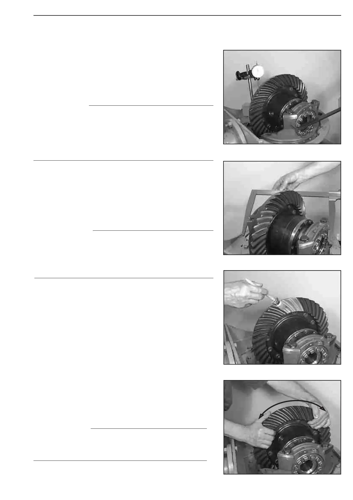
Adjust Backlash - Bevel gear set = 0,27 ... 0,33 mm
Bearing torque - Differential bearing T = 3 ... 4 Nm
and
Yoke width = 472 - 0,2 mm (Figure 290 ... 291):
Determine the backlash by the alternating adjustment of the two
adjusting nuts (Figure 290).
Roll crown wheel several times in both directions over the drive
pinion.
Compare the obtained contact pattern with the Examples of Con-
tact patterns, (See next pages, examples of
gear-tooth-contact patterns
Check Contact pattern (Figure 292 ... 293) !
Cover some driven and driving flanks of the crown wheel with
marking ink.
(S) Plastic mallet 504196
(S) Crow bar 504209
(S) Magnetic stand 504171
(S) Dial indicator 504172
(S) Precision micrometer 509260
Now, adjust both adjusting nuts further for about 1 notch.
Adjust Backlash
Adjust the adjusting nuts without greater force - differential
bearing must not yet be preloaded, however must be abso-
lutely playfree! To ensure this, rotate the differential during
the adjustment procedure several times as well as relax the
bearing by tap ping onto both bearing brackets (use plastic
mallet)!
We know from experience that by adjustment of the two
adjusting nuts for about 1 notch each, the required bear-
ing torque of the differential bearing as well as the bearing
bracket dimension is obtained ! Check bracket dimension
and backlash once more and correct if necessary.
NOTE
In case of a contact pattern deviation, a measuring error
has been made at the determination of the shim (Figure
258), which must be absolutely corrected!
NOTE
NOTE
Figure 293
Figure 292
Figure 291
Figure 290