SHOP MANUAL
Ch 6 page 24
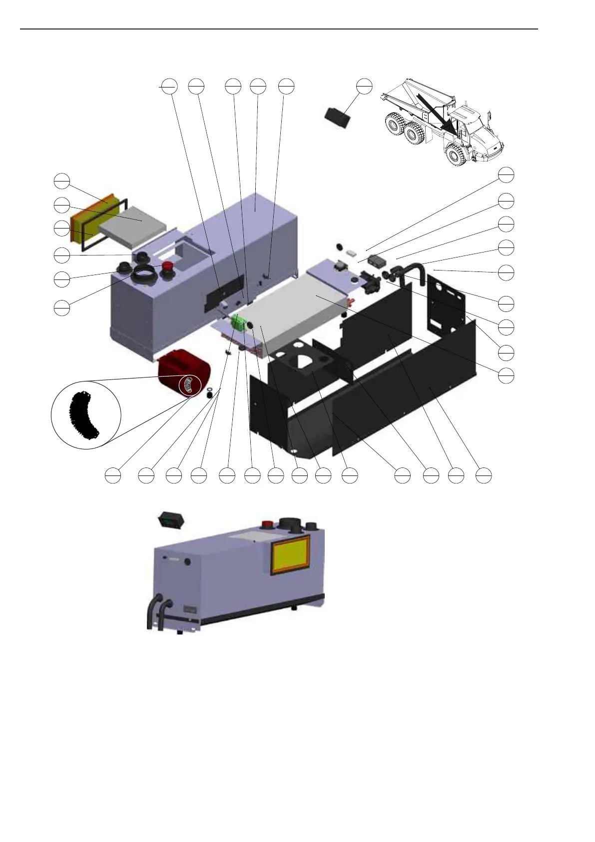
ELECTRICAL SYSTEM
1
4
2
1
3
1
4
3
5
1
6
1
7
3
8
1
9
1
10
2
11
2
12
1
13
1
14
1
15
1
16
1
17
1
18
2
19
1
20
1
21
2
22
1
23
2
24
1
25
1
26
1
27
1
28
1
29
1
30
1
31
1
32
1
33
1
34
1
35
1
Pos. Qty Description
1 4 GROMMET
2 1 INSULATION FRESH AIR DOOR
3 1 INSILATION SIDE
4 3 SPACER M4x25
5 1 RED CAP D50mm
6 1 INSULATION REAR
7 3 HOSE NOZZLE
8 1 COOLING/HEATCOIL
9 1 LEVER
10 2 SEAL
11 2 DRAIN VALVE
12 1 SEAL FRESH AIR
13 1 FRESH AIR DOOR
14 1 EXPANSION VALVE
15 1 INSULATION
16 1 INSULATION
17 1 BLOWER 24v
18 2 MICRO SWITCH
19 1 90 REDUCTION HOSE
20 1 INSULATION
21 2 GROMMET
22 1 INSULATION
23 2 SONDE
24 1 EVAPORATOR HOUSING
25 1 MOTOR 24v
26 1 THERMOSTAT 2 PINS
27 1 SONDE
28 1 FILTER FRESH
29 1 HARNESS
30 1 WATER VALVE 24v
31 1 HOSE NOZZLE
32 1 HOSE 16x24
33 1 FILTER RECIRCULATION
34 1 INSULATION
35 1 ATC 24v KIT
Fan speed
regulator
Heater unit exploded
To get access to service work for the heater and AC unit, following this description:
1 Remove the chair from cabine
2 Remove plastic panels covering the unit
3 To get inside of unit, remove the front steel plate.
If complete unit have to be disassembled; the AC unit have to be release gas from the AC unit, the pipe and
water hose (in and out) have to be disassembled from the unit.
Disassemble electrical connection.
Disassemble screw who are fasten to the floor bracket.
If new parts needed see in the Parts Catalog
To this figure see
component list next page
Figure 17