Engine
SHOP MANUAL
Ch 1 page 53
Removing the ECU wiring Tier2
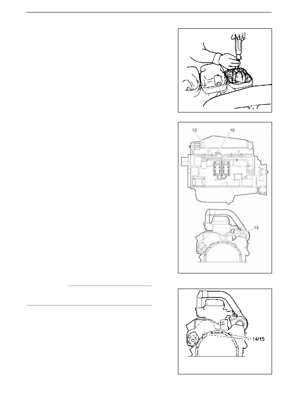
14. Remove engine speed sensor 1 and its
clamps.
15. Remove engine speed sensor 2 and its
clamps.
Drain the coolant from the engine as described in the work de-
scriptions for the cooling system.
2. Wash clean the rocker covers and the area
around them.
3. Remove the inlet pipe between the turbocharger and the air
cleaner.
4. Remove the air line to the compressor. The air line is located
on the left-hand cable duct.
5. Unplug the connectors from the control unit.
6. Remove the rocker covers.
On the 12-litre engine the crankcase ventilation must be removed
before the rocker cover on cylinder 1 can be removed.
7. Disconnect the cables from the unit injectors.
The screws cannot be removed, but they should be unscrewed
as far as possible.
8. Mark the cables with the respective cylinder numbers.
9. Remove the cable duct to which the cables are attached.
The unscrew the cable bushings in the lower rocker covers
and remove the cables.
10. Remove the charge air sensor and its clamps.
11. On engines fitted with an electricallycontrolled fan, separate
the connector on the fan ring, which is connected to the solenoid
valve. Remove the cable clamps as well.
12. Remove the oil pressure sensor and its clamps.
13. Remove the coolant temperature air sensor and its clamps.
Handle the engine speed sensors with care. They
are magnetic and sensitive to impacts.
NOTE
Figure 83
Figure 85
Figure 84