Ch 6 page 7
ELECTRICAL SYSTEM
SHOP MANUAL
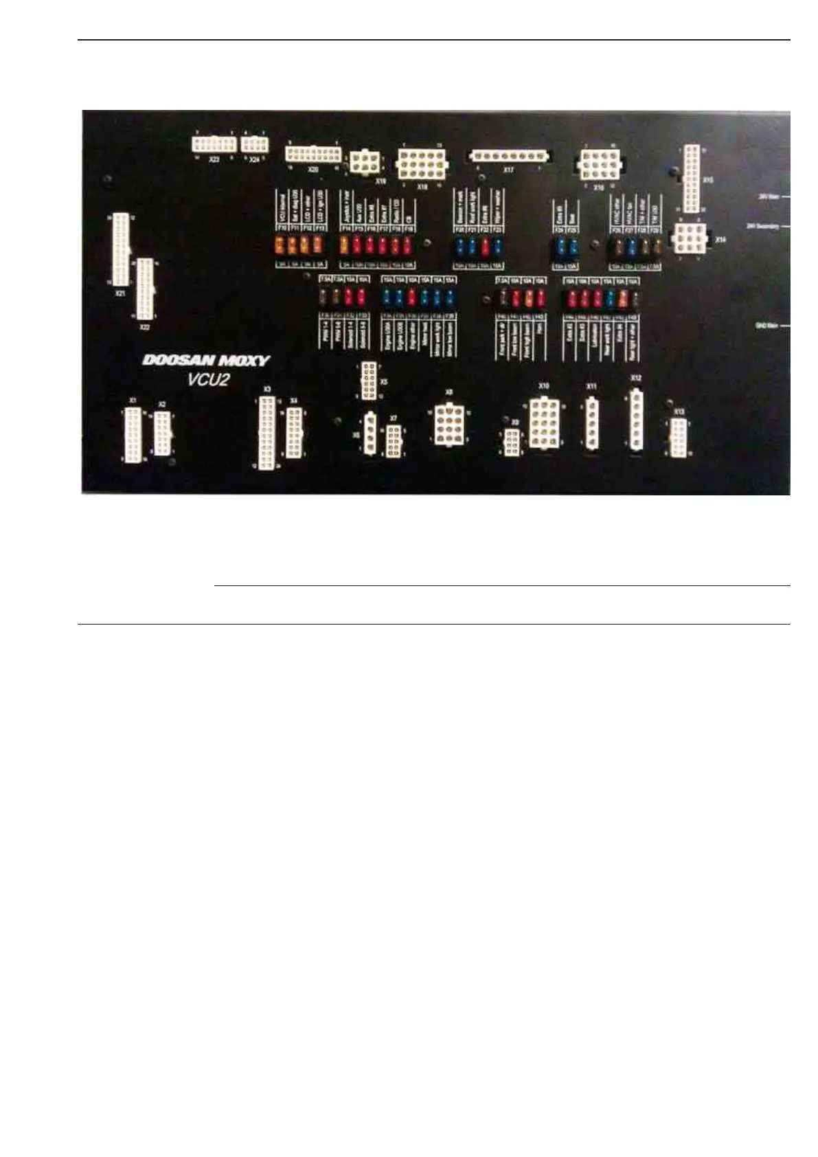
Doosan Moxy VCU 2
Description of the VCU2 functionality
Short main description of the VCU2
VCU2 is the electrical interface for all equipment inside and outside cabin.
VCU2 controls 3 separate CANbuses (CAN1, CAN2 and CAN3):
• CAN1 is connected to: VCU2, Engine, Transmission and LCD unit;
• CAN2 is connected to: VCU2, LCD unit and future SATCOM unit;
• CAN3 is connected to: VCU2, Groeneveld lubrication and WB2 (at rear frame).
VCU2 contains functionality for histogram logging.
(The current CT1 = 400 log values, VCU2 = 800 log values)
VCU2 replaces all onboard relays with electronic controlled outputs.
Short circuit protection is implemented on each output in addition to traditional fuses.
Virtual (software) fuses resets every time the ignition is turned off.
VCU2 reads signals from all devices inside cabin.
Signals are processed in software to control outputs or CANbus data. (Example: Accelerator pedal
position is read by the VCU2 - signal is processed by software - and finally a speed request is sent to the
engine via CANbus)
VCU2 controls most of the hydraulic system using solenoids and pressure transmitters and it reads
pressure from pumps, accumulators, etc.
VCU2 controls brake charge system, park brake, cooling fan, engine brake and tipping system.
The VCU2 is place inside cabin on rear wall right side, covered by interior plate
IF ANY INTERNAL FAILURE OCCUR, THE VCU2 SHOULD BE REPLACED FOR A NEW ONE.
NOTE
Figure 1