SHOP MANUAL
Engine
Ch 1 page 42
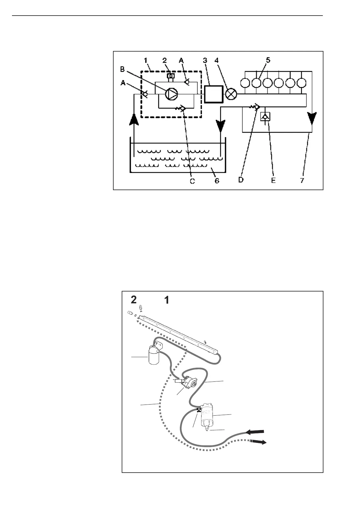
Fuel system Tier2 (PDE)
1 Feed pump
2 Hand pump
3 EMS control unit
4 Fuel filter
5 Cylinders
6 Fuel tank
7 Return line for excess fuel
A Check valve
B Gear pump (feed pump)
C Safety valve
D Pressure relief valve
E Drain nipple
Schematic diagram of the fuel system Tier2
Overflow valve
The purpose of the overflow valve is to limit the pressure in the
fuel system and continuously vent it. The overflow valve ensures
that the fuel circu lates round the system and that there is always
fuel in the injection pump for cooling, lubrication and injection.
Opening pressure is 0.6 - 0.8 bar.
Working pressure is approx. 1 bar.
1 Fuel rail
2 Pressure relief valv
3 Fuel filter
4 Feed pump / hand pump
5 Shut-off cock
6 Oil hose water filter - feedpump
7 Water separating prefilter
8 Retur line
9 Drain valve
Supply from tank
Retur to tank
3
4
8
6
7
5
9
Figure 66
Figure 67