SHOP MANUAL
DRIVE LINE
Ch 3 page 30 Ch 3 page 31
DRIVE LINE
2
3
4
6
5
1
7
2
1
1
1
2
1
S
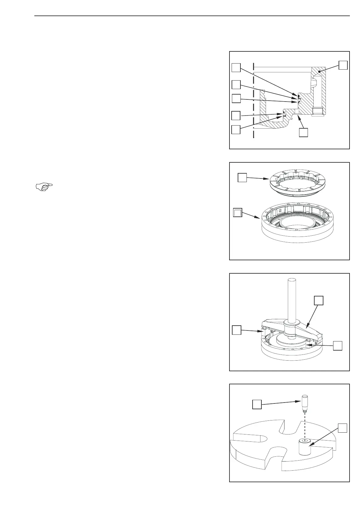
Legend to the sketch:
1 = Brake housing
2 = Guide ring
3 = Backup ring
4 = U-ring
5 = U-ring
6 = Backup ring
7 = Pressure connection
Insert the piston (1) into the brake housing (2).
Apply sufficiently oil onto the sliding surfaces of the
piston or backup rings, U-rings and guide ring
(use W-10 oils)!
Mount the piston by means of the back-off fixture (S) until
contact cautiously.
(S) Sliding pads 514644
(S) Two-armed puller 514673
(S) Support shim 514667
Insert the pins (1) into the assembly fixture (S) until contact.
(S) Assembly fixture 514662
Pre-assemble the return mecanism
Figure 72
Figure 71
Figure 70
Figure 69