SHOP MANUAL
DRIVE LINE
Ch 3 page 32 Ch 3 page 33
DRIVE LINE
X
1
2
3
4
5
1
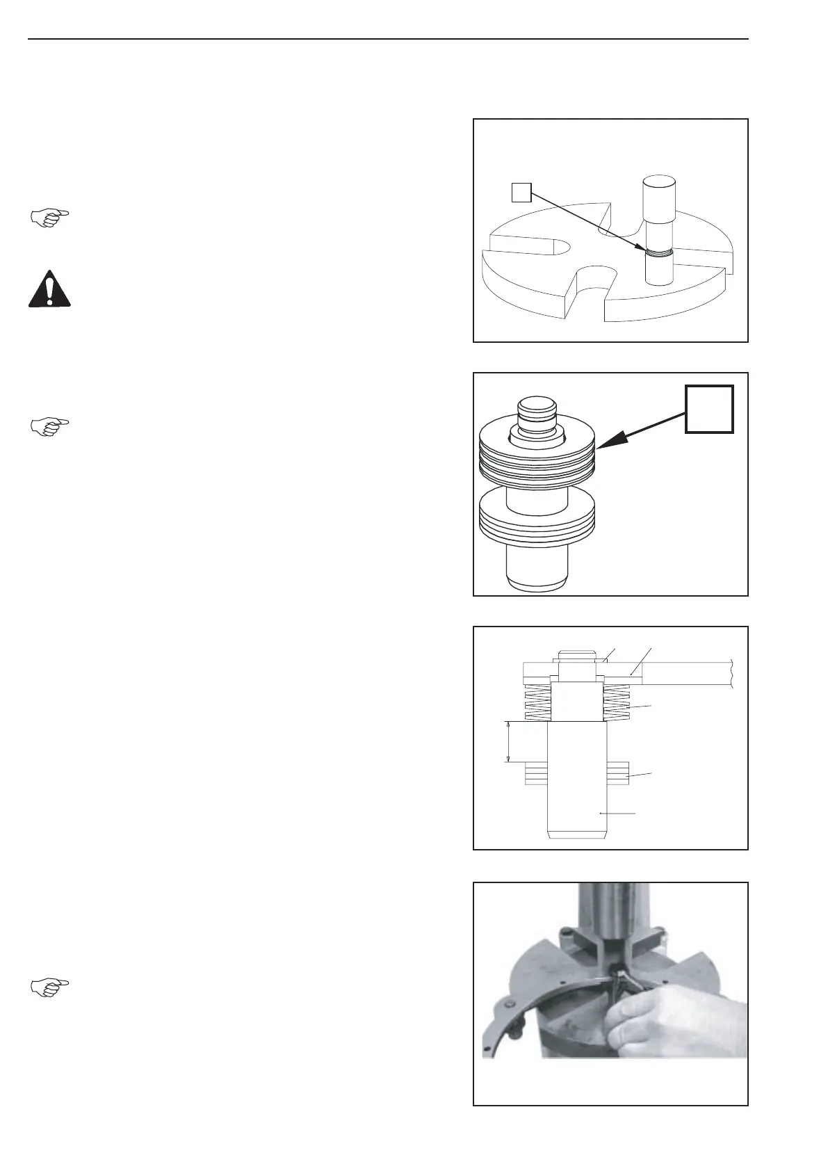
Press 4 gripping rings (1) onto the pins until contact on the
assembly fixture (S).
The exact installation dimension (see Sketch, Fig. 75)
of the gripping rings is obtained when using the speci
fied assembly fixture!
Observe the installation position, install gripping rings
with the orifice offset by 180° to each other!
Mount 7 cup springs (1) onto the pin.
Pay attention to the installation position of the cup
springs, see below sketch (see Sketch, Fig. 75)!
Legend to the sketch:
1 = Pin
2 = Gripping rings
3 = Cup springs
4 = Support shim
5 = Circlip
X = Installation dimension Gripping rings 8.2 +0.3mm
Insert the preassembled pins into the support shim and fix it by
means of the circlip.
(S) Clamping pliers 514669
Pay attention to the clearance of the cup springs!
Figure 75
Figure 74
Figure 73
Figure 76