SHOP MANUAL
DRIVE LINE
Ch 3 page 32 Ch 3 page 33
DRIVE LINE
1
2
1
2
2
1
3
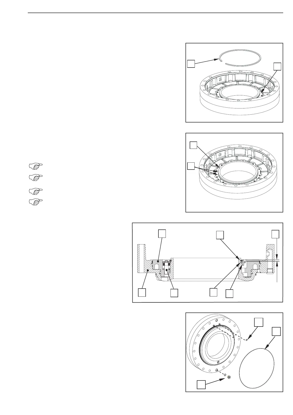
Insert the preassembled support shim (1) into the piston and
fasten it by means of the circlip (2).
Drive 6 slotted pins (1) for locking of the circlip into the bore
holes of the support shim.
(S) Drift mandrel 514668
Wet the slotted pin at extremities with grease!
The circlip opening (2) must be located between two
slotted pins!
Always use new slotted pins!
See Sketch Fig. 79 for installation position and installa
tion dimension of the slotted pins 79!
Legend to the sketch:
1 = Brake housing
2 = Piston
3 = Resetting
4 = Circlip
5 = Support shim
6 = Slotted pin
X = Installation dimension 4.0 +0.5mm
Grease the O-Rings (1) and insert it into the pressure oil
supply bore.
Grease the O-Ring (2) and insert it into the annular groove.
Install the screw plug (3) with a new O-Ring
Tightening torque ....................................... MA = 60 Nm
Figure 80
Figure 79
Figure 78
Figure 77