SHOP MANUAL
HYDRAULIC
Ch 5 page 34 Ch 5 page 35
HYDRAULIC
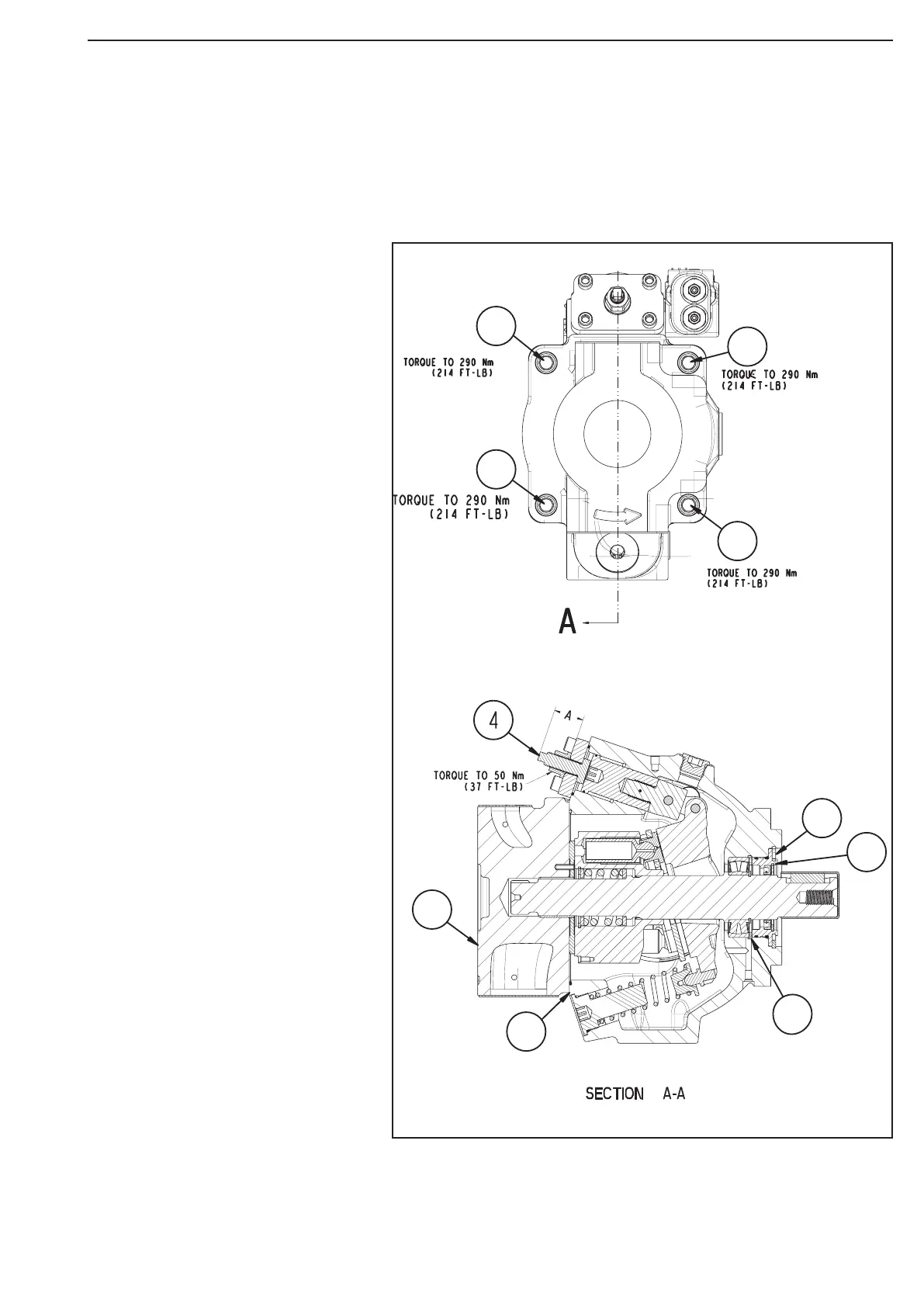
1.
Take the dimension A – top of
max. volume stop screw to servo
cover.
2.
Screw in the max. volume screw 4
as far as possible.
3.
Loosen the rear cover bolts 1 so that
there is approximately 5 mm between
rear cover 2 and housing 3.
4.
Disassemble snap ring 5 and pull
shaft seal carrier 6 with two screw
drivers.
( do not dam-age the shaft seal)
5.
Disassemble snap ring 7 and pull
out the shaft with the bearing.
6.
Put in the new shaft assembly and
the snap ring 7.
7.
Put in seal carrier 6 and snap ring 5.
(Carefully, do not damage the shaft
seal)
8.
Readjust the max. volume screw 4
with dimension A and fasten the nut
(torque 50 Nm).
9.
Fasten rear cover bolts 1 with 290
Nm.
1
1
1
1
5
6
7
3
2
Pump, disassemble - assemble the shaft
Disassembly of the pump in the warranty period is not allowed. In this instance the period of guarantee is
not valid.
Figure 17