SHOP MANUAL
Ch 6 page 16
ELECTRICAL SYSTEM
Description of the main electrical system.
General description
Voltage
The truck has a 24V system.
The batteri ÷ is used as ground connection.
Supply
Two batteries, each 12V/230Ah, are connected together in
serial connection to provide the system with 24V. The batteries
are located in the right hand side fender.
A 28V/100A alternator is used to charge the batteries. The
alternator is located on the front of the engine.
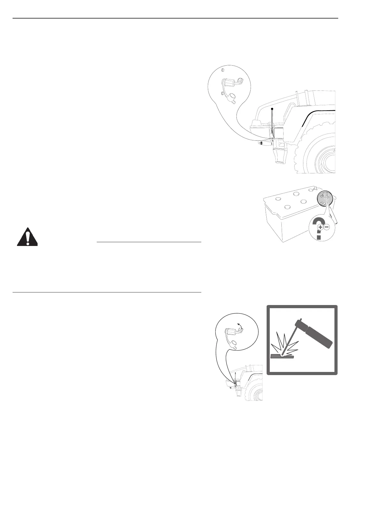
Battery main switch
A main switch is connected on the batteri + supply cabel.
The batteri main switch is located in the left hand side fender.
Fuses
The fuses are located on the VCU2 inside the cab, behind the
cover on the back wall + “junction” box in front left fender.
Welding on the dump truck
The transmission and the engine are equipped with electronic
control units. Before welding on the dump truck:
1. Disconnect batteries.
2. Unplug the connector on the electronic control units for the
engine and the transmission.
The control units are located in the wall behind the seat.
3. Earth point should be less than 1 m from welding point.
4. There should not be sealings, bearings or wiring harness
between the welding point and the earth point.
On
Off
Figure 9
Figure 8
Never turn off battery main switch when engine is running
Never turn off battery mainSwitch when ignition is on
Leave battery main switch on for atleast 5 minutes after
engine has completely stopped.
WARNING