SHOP MANUAL
SHOP MANUAL
LUBRICATION SYSTEM
Ch 4 Page 10 Ch 4 Page 11
LUBRICATION SYSTEM
Grease pressure switch
The grease pressure switch notifies the control unit that sufficient pressure has been built up during the pump-
ing phase stops the pump. When the required pressure is not reached, the pumping phase is only ended after
reaching the set maximum pumping time and an alarm will follow.
Preferably the grease pressure switch is mounted on the distribution block, located the farthest from the pump
(on DA series is mounted o the last distribution block, on the rear part of the rear frame). This is done to be sure
that the required grease pressure of 100 bar also reached the last distribution block.
The switch pressure on the DA series is 100 bar standard.
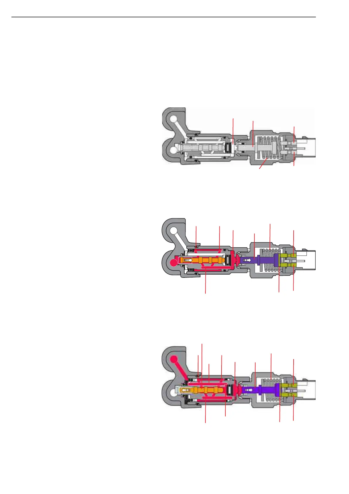
Principle of operation of pressure switch
Phase 1 - during this phase, both channels A and
B are not under pressure. There is no pressure in
chamber (1). Spring (10) pushes switch plunger (2)
to the left. The electrical contact (3 and 4) is open.
Phase 2 - during pumping phase A grease is
pressed into channel A. While the grease pressure
built up, piston (6) is pushed to the right. Chamber
(1) is connected to channel A (through the channels
7, 8 and 9).
As soon as the pressure in chamber (1) is more
than the pressure force of the spring (10), plunger
(2) goes to the right. The electrical contact (3 and 4)
is closed by the contact plate (5).
During the pressure decrease phase, as soon as
the grease pressure in channel A is lower than the
pressure force of the spring, the connection of the
electrical contact is broken.
A
B
10
3
45
2
1
8
9
7
Phase 3 - during pumping phase B grease is
pressed into channel B. While the grease pressure
built up, chamber (11) fills with grease (through
channel 12). The grease pressure pushes piston (6)
is pushed to the left. Because of that the channel
(8) is opened, causing the grease to flow to cham-
ber (1) tothrough channel (7) and channel (9).
As soon as the pressure in chamber (1) is greater
than the pressure force of the spring (10), plunger
(2) goes to the right. The electrical contact (3 and 4)
is closed by the contact plate (5).
During the pressure decrease phase, as soon as
the grease pressure in channel B is lower than the
pressure force of the spring, spring (10), the con-
nection of the electrical contact is broken.
1
B
A
2
10
4
3
B
4
5
3
10
21
87
12
11
9
6
Figure 12
Figure 11
Figure 10