SHOP MANUAL
DRIVE LINE
Ch 3 page 140 Ch 3 page 141
DRIVE LINE
CONTACT PATTERN EXAMPLES OF GLEASON
TOOTH SYSTEM
Field of application:
The contact pattern examples are applicable for all bevel gear sets
in MT and MS axles which have a ratio
between 1.5 < i < 6.
Furthermore, the examples are only valid for ground bevel gear
sets.
(The examples are just partly applicable for lapped contact pat-
terns).
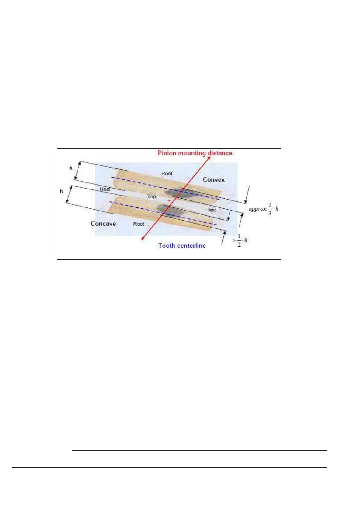
Ideal contact pattern fig. 411
Contact pattern setting:
The contact patterns are viewed on the crown wheel flanks.
The contact pattern must be tangent to the middle of tooth (tooth centerline), otherwise it is too
close to the tooth top or root. Furthermore, the contact pattern should cover at least 50% of the
flank in h-direction (inspection criterion).
General:
By shifting the pinion the contact pattern is moved to the tooth or top.
Pinion mounting distance in + : = reduce pinion shim thickness
Pinion mounting distance in - : = increase pinion shim thickness
Flank glossary:
Convex flank = Drive side
Concave flank = Coast side
Toe = Crown wheel inner side
Heel = Crown wheel outer side
The following pages (141 - 142) describe three different examples of contact patterns!
NOTE
Figure 424