SHOP MANUAL
HYDRAULIC
Ch 5 page 52 Ch 5 page 53
HYDRAULIC
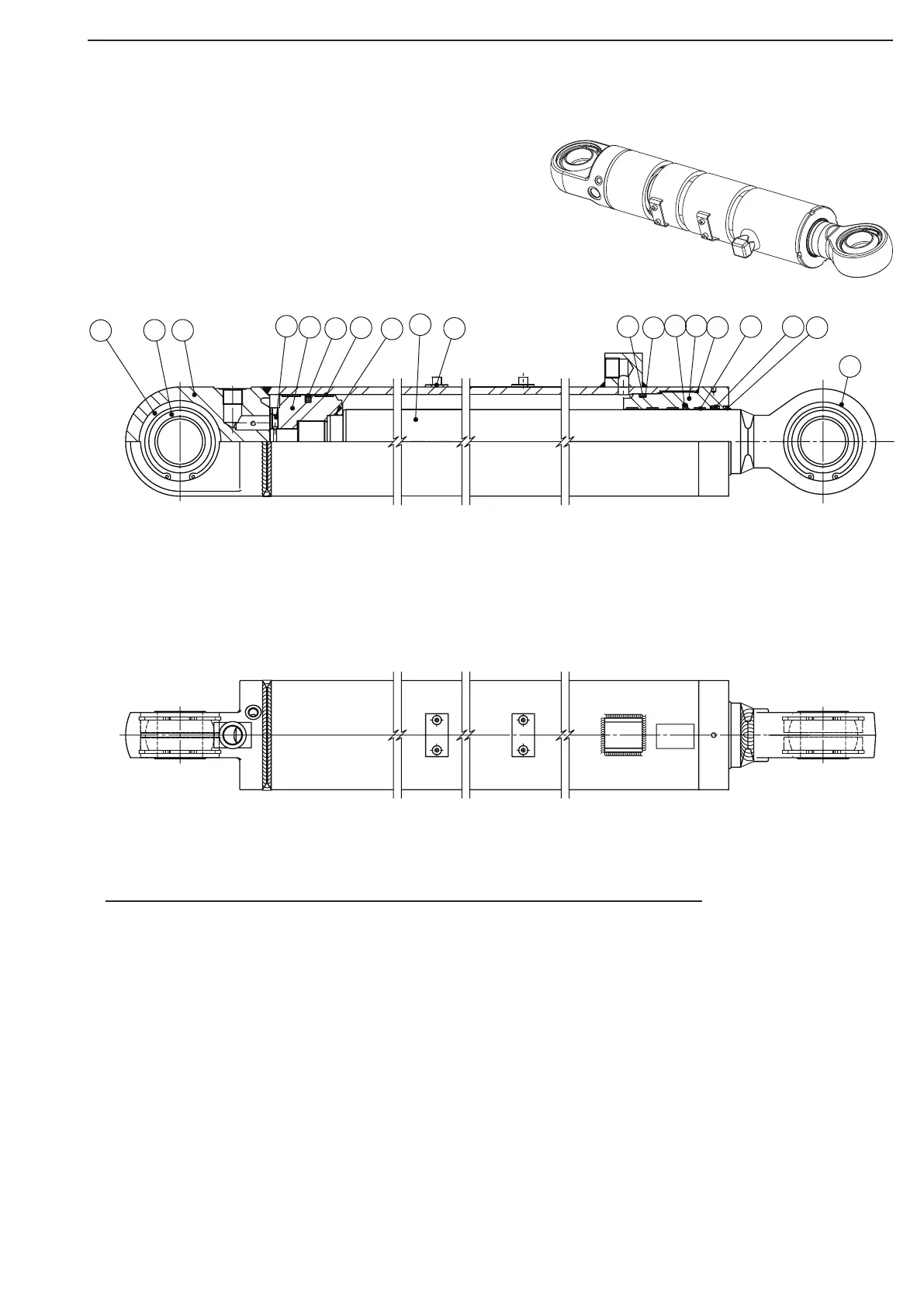
Tilt cylinder, sectional drawing.
Tilting cylinder ass'y
Pos Qt’y Description DA30 DA40
1 4 Internal circlip Ø105mm Ø105 mm
2 2 Spherical insert
3 1 Cylinder end forged Ø115mm Ø125 mm
4 1 Hexagonal socket screw M8x20 M8x20
5 1 Piston head Ø115mm Ø125 mm
6 1 Seal
7 1 Bearing strip
8 1 O-ring
9 1 Piston rod
10 2 Tube clamp weld on
11 1 O-ring
12 1 Back up ring
13 1 Seal
14 1 Screwed gland
15 1 O-ring
16 4 Bearing strip
17 1 Rod seal
18 1 Wiper
19 1 Rod end
5
7
Figure 40
3
4
1812
82
6
1
10
11
15
16 17
19