SHOP MANUAL
SHOP MANUAL
LUBRICATION SYSTEM
Ch 4 Page 6 Ch 4 Page 7
LUBRICATION SYSTEM
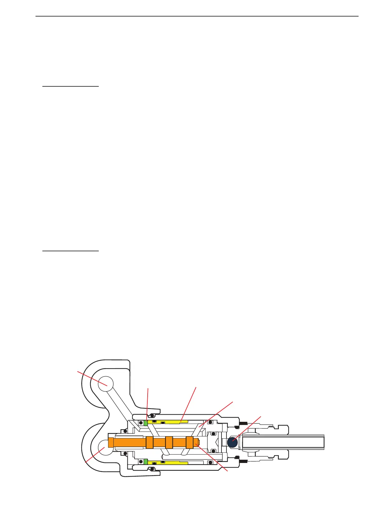
Principle of operation of metering unit
Two grease chambers are located in a metering unit (on for each primary grease line, A and B). These cham-
bers are filled with an exact amount of grease. When the actual greasing takes places through one of both
chambers, the grease is pressed from the chambers to the relevant greasing point.
Greasing cycles
Every greasing cycle consists of four phases.
The greasing cycles as carried out alternately by the grease lines A and B. The 5/2 way valve, which is inte-
grated in the pump housing, determines which primary grease line is connected to the pump and which is con-
nected to the grease reservoir.
Greasing cycle A
Pumping phase: in this phase the grease is pumped from the reservoir, through primary grease line A, to the
distribution blocks.The pumping phase ends when the pressure switch reaches a predetrmined level. During
the pumping phase, the metering units press a certain amount of grease (the dosage) through the secondary
grease lines to the grease points.
Pressure retaining phase: a period in which the pressure primary grease lines is maintained at a certain pres-
sure. During the pressure retaining phase, the metering units can deliver the grease dosage, which was not yet
delivered during the pumping phase.
Pressure decrease phase: in this phase, the pressure in the primary grease line is decreased through the 5/2
way valve. To accomplish this, the control unit energizes the 5/2 way valve, so the grease pressure in the pri-
mary grease line A is decreased and the grease flows back to the reservoir. When the greasing system needs
more time to build up the required grease pressure (because of low temperature or grease with a high viscos-
ity), the system will also need more time to decrease that same pressure.
Pause phase: the lenght of the pause phase is equal to the pre-determined cycle-time minus the lenght of the
other phases. When the cycle-time is adjusted too short to carry out a complete greasing cycle, the program
will ignore the cycle-time. However the pause phase will be omitted, because the pre-determined cycle-time is
exceeded. The greasing system begins directly with the first phase of the next greasing cycle.
Greasing cycle B
Greasing cycle B begins when the control unit restarts the pump. During pumping phase B and pressure retain-
ing phase B, the control unit still has the 5/2 way valve energized, causing the pump to be connected to primary
grease line B. Primary grease line A is shut off from the pump during these phases and connected to the reser-
voir. During phase B pressure decrease, the control unit de-energizes the 5/2 way valve, so the grease pressure
in the grease line B decreases and the grease flows back to the reservoir.
External plunger
Grease channels
Non-return valve
Internal plunger
Chambers
Primary grease
line A
Primary grease
line B
Internal greasing metering
unit overview
Figure 5