Ch 6 page 19
ELECTRICAL SYSTEM
SHOP MANUAL
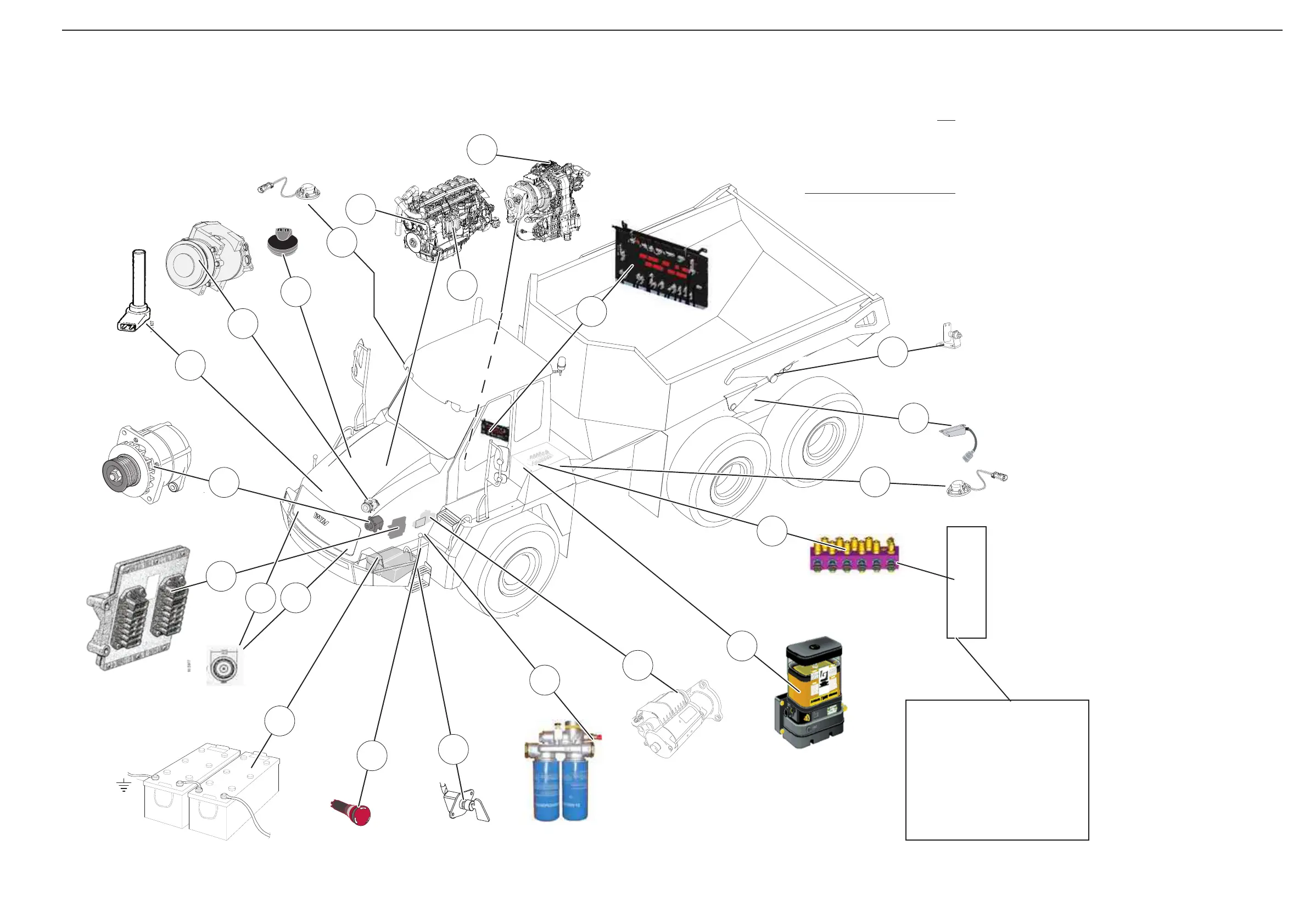
Electrical parts view
+
+
P
U
S
H
Test block:
140 Pump 1 pressure
141 Pump 1 pressure
142 Front brake pressure
143 Rear brake pressure
144 Park brake pressure
145 Tilt cylinder pressure
X-BS VCU2 El.central
130 Main switch
131 Battery
140 Hydraulic testpoint
171 Engine emergency switch off
172 Exp tank level
173 Air filter sensor
200 Diesel tank level sensor
201 Hydr-t-level sensor
210 Engine Control S8 / S6
220 Transmission control unit
221 Transmission pressure sensor
230 Central lubrication main unit
350 Compressor, A/C (clutch)
340 Horn Lhs
341 Horn Rhs
420 WB2T Sensor input WDB unit
424 Body tilting sensor
X-BS VCU2 El.central
E.P Alternator
E.P Starter
Principal components
131
E.P
130
230
350
420
221
140
141
142
143
144
145
210
X-BS
E.P
140
173
172
201
200
220
350
210
340
341
424
171
E.P = Engine Part (Part
is included in engine
assembly)
Component position
Go to the Pos reference
list to find place on the
circuit drawings parts be-
long to.
NOTE
Figure 12