SHOP MANUAL
Ch 6 page 22
ELECTRICAL SYSTEM
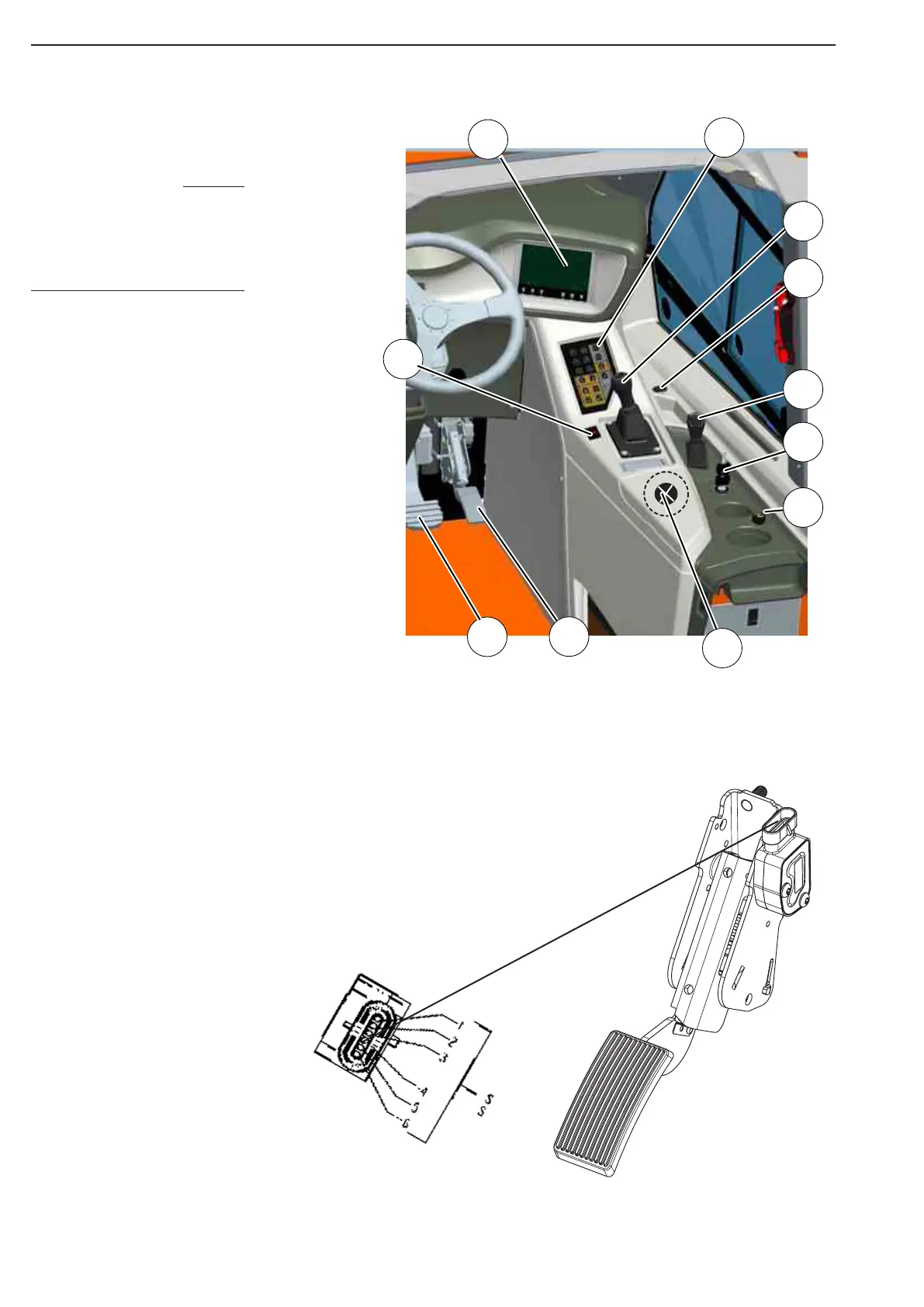
41 Operation switch panel
42 Tip joystick
43 Foot brake pedal
44 LCD unit
46 Accelerator pedal
47 Park brake switch
48 Gear selector
49 Ignition key switch
51 Cigarette lighter
52 12V outlet
D2 USB / LCD connector
44
41
48
42
49
43
47
51
46
52
D2
El.system, Cab inside
Go to the Pos reference
list to find place on the
circuit drawings parts be-
long to.
Accelerator pedal Pos 46 522575
Accelerator pedal POS 46 Function
wires 4-pin UMNL
male
pin 1 (Blue) pin 2 GND 2
pin 2 (White) pin 4 Output Signal 2
pin 3 (Yellow) pin 1 +5V Supply 2
pin 4 (Red) pin 1 +5V Supply 1
pin 5 (Black) pin 2 GND 1
pin n (Green) pin 3 Output Signal 1
Electrical equipment inside cab
NOTE
Figure 15
Figure 14