SHOP MANUAL
DRIVE LINE
Ch 3 page 66 Ch 3 page 67
DRIVE LINE
1. Adjust the caliper by reducing the caliper-to-disc
clearance to ZERO.
Refer to Table A for the adjusting direction.
2. Check that the load plate fully contacts
the lining backing plate.
3. Use a 6 mm Allen wrench to increase the disc
clearance SEVEN CLICKS, which sets the initial
clearance.
Figure 178.
4. Install the adjuster plug and washer. Tighten the
adjuster plug to 8-12 lb-ft (11-17N•m).
Figure 179.
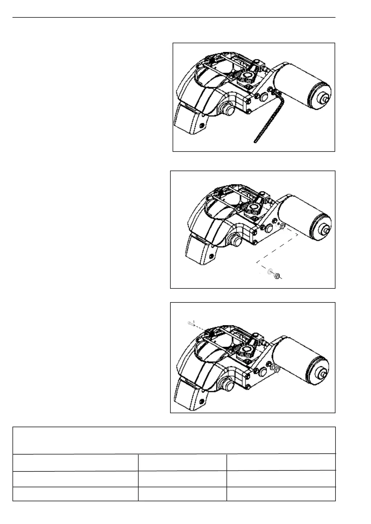
5. Unhinge the stabilizer bar and return it to position.
Install the stabilizer bar pin and cotter pin.
Figure 180.
6. Apply and release the brake assembly 15-20
times to allow the adjuster to set the final
caliper clearance.
7. Check the adjusted chamber stroke length.
Refer to the next pages
Adjust the Initial Caliper Clearance
Table A: Increasing and Decreasing Disc Clearance
Caliper Identification Increase Disc Clearance Decrease Disc Clearance
LH Hydraulic Release Brake Assembly Counterclockwise Clockwise
RH Hydraulic Release Brake Assembly Clockwise Counterclockwise
Figure 180
Figure 179
Figure 178