Ch 6 page 51
ELECTRICAL SYSTEM
SHOP MANUAL
Engine electrical components.
Rotor Slip rings
The slip rings must be bright metal across their
whole surface. Dull slip rings indicate bad
contact with the brushes. The slip rings can be
accessed after removing the charge regulator.
Resistance
Measure the rotor resistance using an ohmmeter
between the slip rings.
Correct resistance is 11.2 W for 90 A.
Correct resistance is 8.4 + 0.4 W for 65 A.
When measuring the strap between the slip rings
and the core, the ohmmeter must show infinite
resistance, at least 10 MW.
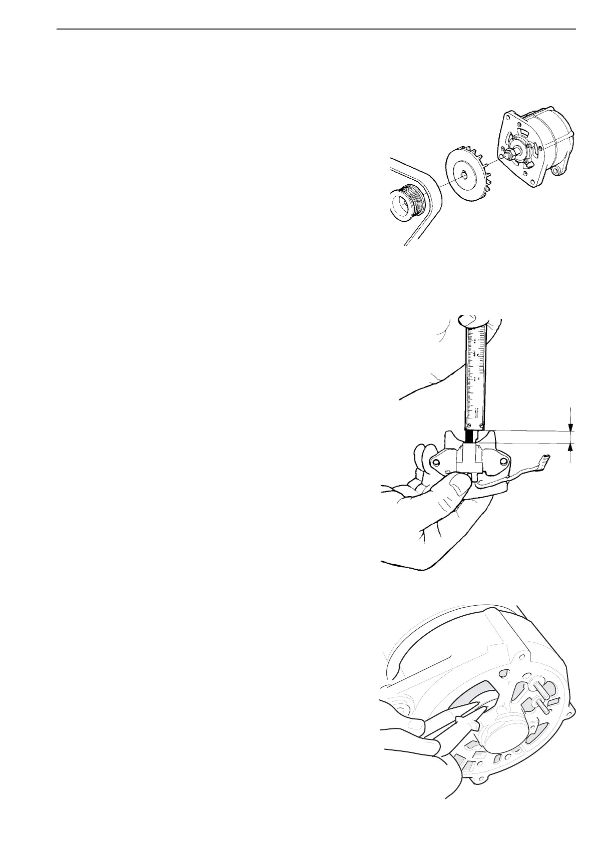
Brush length
The brush holder is fixed on the charge
regulator. The brushes must be checked for
damage and length. The ends must be bright and
rounded off so they fit against the slip rings.
Brush length is measured between the end of the
brush and the brush holder.
The correct length is >2.5 mm for 90A.
Alternator
Specifications
Alternator 28V 35 - 100A
Output at 6000 rpm. 2500 W
Gear ratio 3,5:1
Number of poles 8
Resistance in rotor approx. 11.2 ohm +/- 5%
Resistance in stator, Phase-Phase 0.085 ohms +/- 0.001
Brushes, min, length >2.5 mm
Slip rings, min. diameter >13.8 +/- 1 mm
Tightening torque, belt pulley 65 Nm
Batteries Qty 2x12V, series connected
Ground connection Negative
System voltage 24V
Figure 28
Figure 27
Figure 29