SHOP MANUAL
Engine
Ch 1 page 102
Assembling piston and connecting rod
1. Clean the piston and its rings thoroughly
without scratching the sides of the ring
grooves. The oil holes in the piston should be
cleaned using a suitable drill.
2. Make sure the piston ring gaps do not exceed
the permitted limit.
Place the piston rings in the cylinder liner
and measure the gap using a feeler gauge.
For permitted gap, see section entitled
Specifications, piston rings.
Make sure the piston ring gaps do not exceed the permitted limit.
Place the piston rings inside the cylinder liner and measure the
gap with a feeler gauge. Permitted gap according to values listed
below.
Maximum piston ring gap for 9 and 13 litre engines with XPI:
Compression ring 1 (upper) 0.9 mm
Compression ring 2 (lower) 1.1 mm
Oil scraper ring 0.8 mm
Maximum piston ring gap for 9 and 13 litre engines with PDE:
Compression ring 1 (upper) 0.9 mm
Compression ring 2 (lower) 1.8 mm
Oil scraper ring 0.8 mm
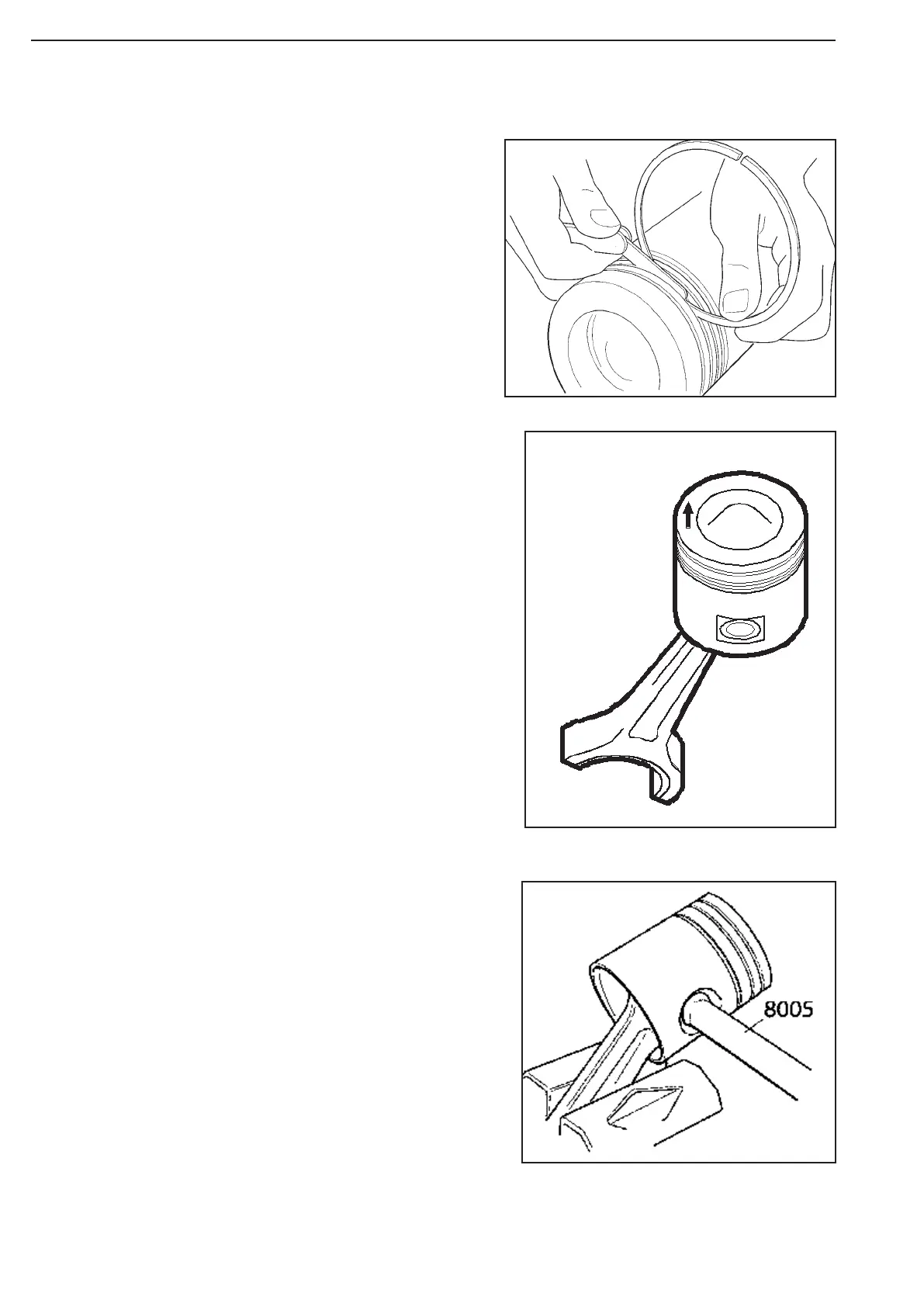
3. Fit the piston rings using tool 8395. The
oil scraper ring has an expander. Pistons
rings marked with TOP must be turned with
TOP face up.
4. Oil all the bushings, the gudgeon pin hole
and the gudgeon pin before assembling.
5. Place one of the retaining rings in the piston.
6. Turn the piston and connecting rod as
illustrated. The arrow mark should point
forward on the engine.
7. Insert the gudgeon pin using tool 8005 and
fit the second retaining ring for the gudgeon
pin.
Figure 195
Figure 196
Figure 197