SHOP MANUAL
DRIVE LINE
Ch 3 page 34 Ch 3 page 35
DRIVE LINE
1
2
1
2
3
4
5
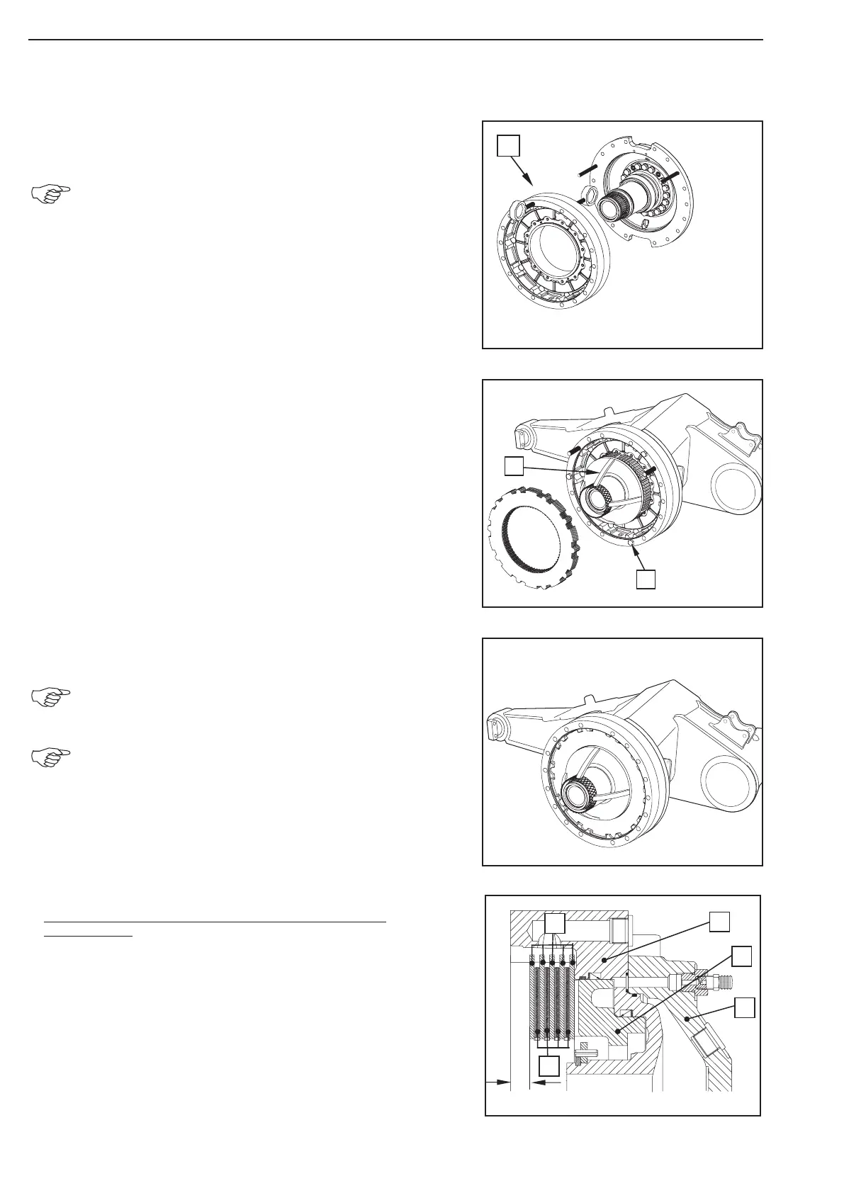
By means of the lifting tackle locate the brake carrier (1)
until contact is obtained.
Observe the radial installation position of the hub
carrier!
Fasten the brake carrier by means of three hexagon screws (1)
provisionally to the brake carrier.
Mount (2) the fixture onto the hub carrier.
(S) Spline mandrel 519429
Install the outer and inner discs alternately,
starting with an outer disc.
Disc arrangement (see Sketch, Fig. 84) and clearance
(see Fig. 84 and 85)!
Oil the disc to ZF Lists of Lubricants TE-ML 05!
Determination of the clearance for new lined discs
(inner discs):
Legend to the sketch Figure 84 and 85:
1 = Brake housing
2 = Piston
3 = Brake carrier
4 = Outer discs
5 = Inner discs
6 = Sealing holder
X = Size to determine the clearance
Y = Size to determine the clearance
Figure 84
Figure 83
Figure 82
Figure 81