SHOP MANUAL
DRIVE LINE
Ch 3 page 34 Ch 3 page 35
DRIVE LINE
Y
6
1
1
1
Determination of the clearance for new lined discs (inner discs):
Example:
X ……………………….. = 28.00 mm
Y ……………………….. = 26.60 mm
Clearance = - 1.40 mm
If required, correct the clearance with an adequate outer disc.
Max. clearance for new lined discs: 1.3
+ 0.3
mm
Max. clearance (wear): 4.1 mm
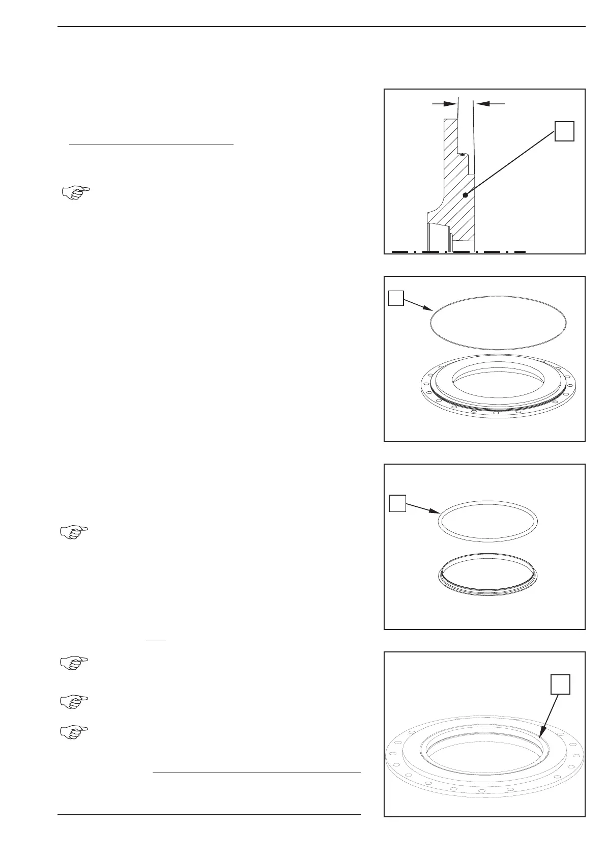
Grease the O-Ring (1) and insert it into the annular groove of the
sealing holder.
Wet O-ring (1) of slide ring seal with spirit and insert into slide
ring guide.
Also wet locating hole of sealing holder (see figure 88) with
spirit.
Any opening of the seal kit necessary for repair work
requires the installation of a new seal kit (slide seal
rings), even if wear limit has not yet been achieved.
Thereupon snap new slide ring seal (1) into sealing ring holder.
Pay attention that sealing surface is in parallel to the
housing surface! The O-rings must be mounted evenly
in the locating hole and must not bulge out of the hole.
The surface of the slide ring seal must not show any
profiled grooves, scratches and other damages!
Also see sketch, Fig. 94 for installation position of the
slide ring seal.
The surface of the slide ring seal must not show any pro-
led grooves, scratches and other damages!
NOTE
Figure 88
Figure 87
Figure 86
Figure 85