Engine
SHOP MANUAL
Ch 1 page 41
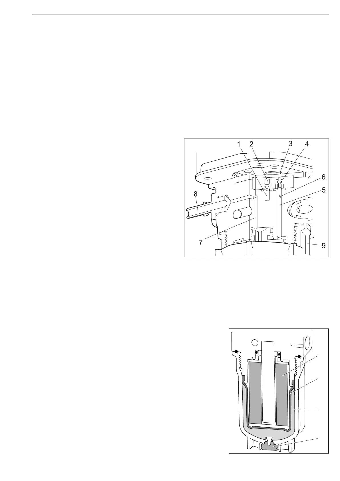
Figure 64 shows a section through the valve block viewed from the side.
Reductant is sucked in through the intake port (1) and via an intake valve (2) to the pump chamber, where
reductant pressure is built up by means of the pump diaphragm (3). Pressurised reductant passes through the
outlet valve (4) and via the port (5) to the reductant filter, which is located under the valve block. If the pressure
exceeds 13 bar, the overflow valve opens via the port (6). Once the reductant has passed the reductant filter, it
is pumped out via the port (7) and outlet (8). The reductant pressure has been reduced and is approx. 10 bar.
1
2
3
4
1 Reductant filter
2 Sealing bladder
3 Damping element
4 Diaphragm valve
1 Port from the reductant filter in the valve block
2 Intake valve
3 Pump diaphragm
4 Outlet valve
5 Port to the reductant filter under the valve block
6 Port to overflow valve
7 Port from the reductant filter under the valve block
8 Connection, outlet for reductant
9 Reductant filter retainer under the valve block
The reductant filter (1), which is located under the valve block, must be renewed in accordance with the speci-
fied inspection interval. If the reductant freezes in the reductant pump at low outdoor temperatures when it is
non-operational, which takes place at approx. -11°C, there is a damping element (3) in the filter retainer that is
compressed when the reductant expands during freezing. A sealing bladder (2) protects the damping element
from coming into contact with the reductant. The damping element and the area around it are ventilated via a
diaphragm valve (4).
Figure 64
Figure 65