SHOP MANUAL
Ch 6 page 6
ELECTRICAL SYSTEM
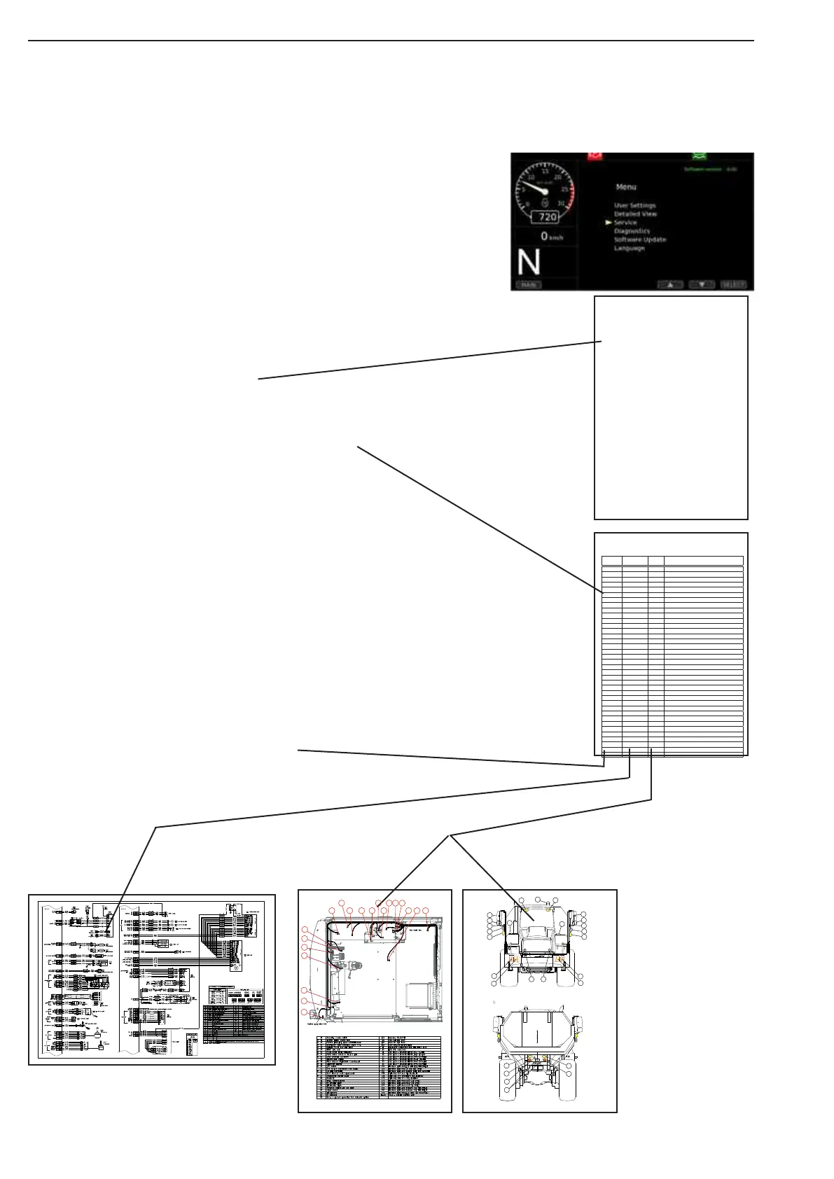
If some malfunction;
first always check on the VCU2 computer LCD display,
diagnostics function.
Find the component
who make the
malfunction
Open the Index list to find the page
hvere the component is described.
Go to page Position Reference List
Find the position number
for component with
malfunction and read out the
Map or Circuit this component
place is belong to
On the Position Reference List is displayd the map or circuit
hvere component are described. Here you find witch place on
circuit and wich map this is described.
Index
Position
reference
list
LCD
Display
Map
Circuit number with
reference place
3B
S44
56
D1
5149
D2
50
42
47 4841
52
43
45A
45B
46
40
S57
55
57
304
303
306
305
324
323
326
325
327
307
310
330
311
331
200
102
412
414
413
103
341
415
101
162
340
411
410
1
1 2 3 4 5 6 7 8 9 10 11 12 13 14 15
A
B
C
D
E
F
G
H
I
J
K
L
M
Position number
Description of el. system ................................................................ 637
General description .................................................................................................................... 637
Welding on the dump truck ......................................................................................................... 637
Battery hazard prevention ........................................................................................................... 638
How to use the electrical documentation .................................................................................... 639
Faultfinding, what to do ............................................................................................................... 639
Practical example ....................................................................................................................... 640
Description of circuit symbols ..................................................................................................... 640
Electrical parts view .................................................................................................................... 642
DA series functions and parameters ............................................. 644
Brake/brake charge system (Accumulators) .............................................................................. 644
WDB Cooling (only on DA40) ..................................................................................................... 644
Emergency Steering system ....................................................................................................... 645
TO BE IMPLENTED: ................................................................................................................... 645
Park brake ............................................................................................................................... .647
Low engine oil pressure .............................................................................................................. 647
Low coolant level ...................................................................................................................... 647
Clogged air filter ........................................................................................................................ 647
Central lubrication pump ............................................................................................................ 647
Charge lamp .............................................................................................................................. 648
Body tip system .......................................................................................................................... 648
Load weighing ........................................................................................................................... 649
Load weighing ........................................................................................................................... 649
Cooling fan control ...................................................................................................................... 650
Quick warmup function ............................................................................................................... 651
Cooldown function ...................................................................................................................... 651
Alternative engine speed ............................................................................................................ 652
Interior light ............................................................................................................................... .. 652
Retarder and Engine brake ......................................................................................................... 652
Emergency Stop ......................................................................................................................... 652
Fuel Heater ............................................................................................................................... .. 653
A/C compressor control .............................................................................................................. 653
Engine electrical components. ....................................................... 654
Spesification of electrical components ....................................................................................... 662
Engine spesification of electrical components ............................ 663
Engine speed sensors ................................................................................................................ 663
Transmission spesification of electrical components ................. 668
Transmission speed sensors ...................................................................................................... 668
Transmission temperature sensors ............................................................................................. 669
Transmission solenoid valves ..................................................................................................... 670
Transmission pressure switch ..................................................................................................... 671
Transmission electric switch ....................................................................................................... 671
Pos. No Circuit and
place ref.
Map No. Description VCU2 text (circuit diagram)
40 1- G4 Steering column switch
41 1- I 5 3B OPBTN2 Operating buttons
42 1- M5 3B Tip joystick
43 1- K4 3B Foot brake pedal
44 1- F11 3B LCD unit
45 1- E15 3B HVAC unit
46 1- J 4 3B Accelerator pedal
47 1- J 4 3B Park brake switch
48 1- L4 3B Gear selector
49 1- I 3 3B Ignition key switch
50 1- E10 3B Alarm buzzer
51 1- A3 3B Cigarette lighter
52 1- A4 3B 12V outlet
53 1- B3 3C 24V/12V converter
55 1- A9 3B CB unit
56 1- D9 Driver seat
57 1- F5 3B Windscreen washer pump
60 G4 3C SIFUI Sensor interface unit
80 1- A5 3A Radio/CD
81 1- A5 3A Climate control panel
82 1- D5 3A RH interior light
83 1- D5 3A LH interior light
84 1- E5 3A-3C Door switch
85 1- E5 3A Wiper
86 1- C4 3A-3C LH speaker
87 1- C4 3A RH speaker
88 1- A14 3A Heater unit relay
100 1- A5 3A Antenna
101 1- B10 3A Roof LH work light
102 1- B10 3A Roof RH work light
103 1- B10 3A Roof beacon/marker light
XXX 2- B14 Starting motor
130 2- C15 Main switch
131 2- D14 Battery bank
140 2- A4 P1 pump
141 2- A4 P2 pump
142 2- A4 Accumulator1 Front brake
Pos reference list
Description of el. system ................................................................ 637
General description .................................................................................................................... 637
Welding on the dump truck ......................................................................................................... 637
Battery hazard prevention ........................................................................................................... 638
How to use the electrical documentation .................................................................................... 639
Faultfinding, what to do ............................................................................................................... 639
Practical example ....................................................................................................................... 640
Description of circuit symbols ..................................................................................................... 640
Electrical parts view .................................................................................................................... 642
DA series functions and parameters ............................................. 644
Brake/brake charge system (Accumulators) .............................................................................. 644
WDB Cooling (only on DA40) ..................................................................................................... 644
Emergency Steering system ....................................................................................................... 645
TO BE IMPLENTED: ................................................................................................................... 645
Park brake ............................................................................................................................... . 647
Low engine oil pressure .............................................................................................................. 647
Low coolant level ...................................................................................................................... 647
Clogged air filter ........................................................................................................................ 647
Central lubrication pump ............................................................................................................ 647
Charge lamp .............................................................................................................................. 648
Body tip system .......................................................................................................................... 648
Load weighing ........................................................................................................................... 649
Load weighing ........................................................................................................................... 649
Cooling fan control ...................................................................................................................... 650
Quick warmup function ............................................................................................................... 651
Cooldown function ...................................................................................................................... 651
Alternative engine speed ............................................................................................................ 652
Interior light ............................................................................................................................... .. 652
Retarder and Engine brake ......................................................................................................... 652
Emergency Stop ......................................................................................................................... 652
Fuel Heater ............................................................................................................................... .. 653
A/C compressor control .............................................................................................................. 653
Engine electrical components. ....................................................... 654
Spesification of electrical components ....................................................................................... 662
Engine spesification of electrical components ............................ 663
Engine speed sensors ................................................................................................................ 663
Transmission spesification of electrical components ................. 668
Transmission speed sensors ...................................................................................................... 668
Transmission temperature sensors ............................................................................................. 669
Transmission solenoid valves ..................................................................................................... 670
Transmission pressure switch ..................................................................................................... 671
Transmission electric switch ....................................................................................................... 671
Pos. No Circuit and
place ref.
Map No. Description VCU2 text (circuit diagram)
40 1- G4 Steering column switch
41 1- I 5 3B OPBTN2 Operating buttons
42 1- M5 3B Tip joystick
43 1- K4 3B Foot brake pedal
44 1- F11 3B LCD unit
45 1- E15 3B HVAC unit
46 1- J 4 3B Accelerator pedal
47 1- J 4 3B Park brake switch
48 1- L4 3B Gear selector
49 1- I 3 3B Ignition key switch
50 1- E10 3B Alarm buzzer
51 1- A3 3B Cigarette lighter
52 1- A4 3B 12V outlet
53 1- B3 3C 24V/12V converter
55 1- A9 3B CB unit
56 1- D9 Driver seat
57 1- F5 3B Windscreen washer pump
60 G4 3C SIFUI Sensor interface unit
80 1- A5 3A Radio/CD
81 1- A5 3A Climate control panel
82 1- D5 3A RH interior light
83 1- D5 3A LH interior light
84 1- E5 3A-3C Door switch
85 1- E5 3A Wiper
86 1- C4 3A-3C LH speaker
87 1- C4 3A RH speaker
88 1- A14 3A Heater unit relay
100 1- A5 3A Antenna
101 1- B10 3A Roof LH work light
102 1- B10 3A Roof RH work light
103 1- B10 3A Roof beacon/marker light
XXX 2- B14 Starting motor
130 2- C15 Main switch
131 2- D14 Battery bank
140 2- A4 P1 pump
141 2- A4 P2 pump
142 2- A4 Accumulator1 Front brake
Pos reference list