SHOP MANUAL
DRIVE LINE
Ch 3 page 102 Ch 3 page 103
DRIVE LINE
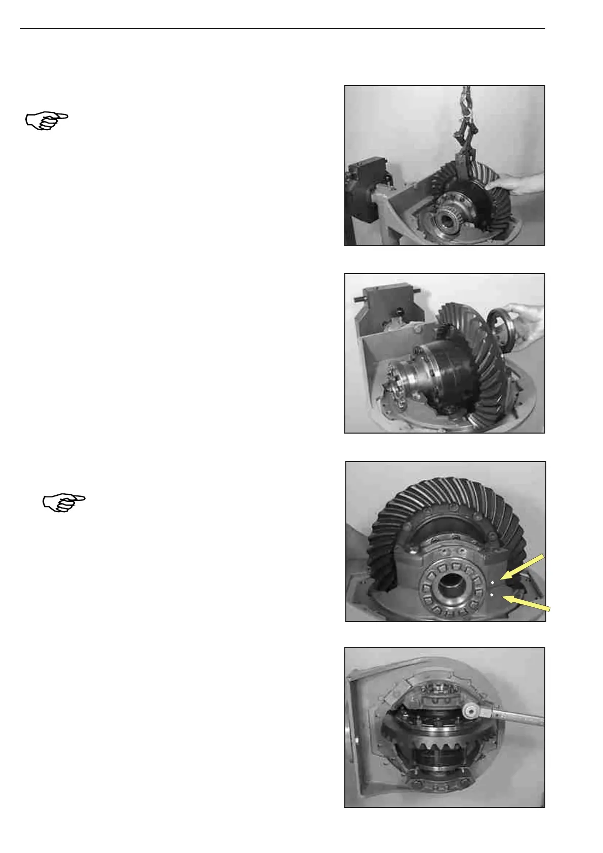
Position differential by means of lifting device in the axle drive
housing and install both bearing outer races.
Pay attention to the position of the sliding pad !
(S) Gripper tongs 505155
Tilt axle drive housing 90° and tighten hex. head screws.
Hex head screw M22/10.9
Loctite No. 262
Torque limit ........................................ 750 Nm
Hex head screw M16/10.9
Loctite No. 262
Torque limit ..........................................280 Nm
Mount both bearing brackets and locate them provisionally by
means of hex. head screws (mount flat washers).
Pay attention to the installation position of the
bearing brackets, see markings (Arrows) !
Wet thread of hex. head screws with
Loctite (Type- No. 262)!
Pay attention to the exact overlapping of the
threaded parts (axle drive housing, adjusting nuts
and bearing brackets !
Free movement of the adjusting nut must be
ensured !
Install both adjusting nuts.
Figure 289
Figure 288
Figure 287
Figure 286