SHOP MANUAL
Ch 5 page 48
HYDRAULIC SYSTEM
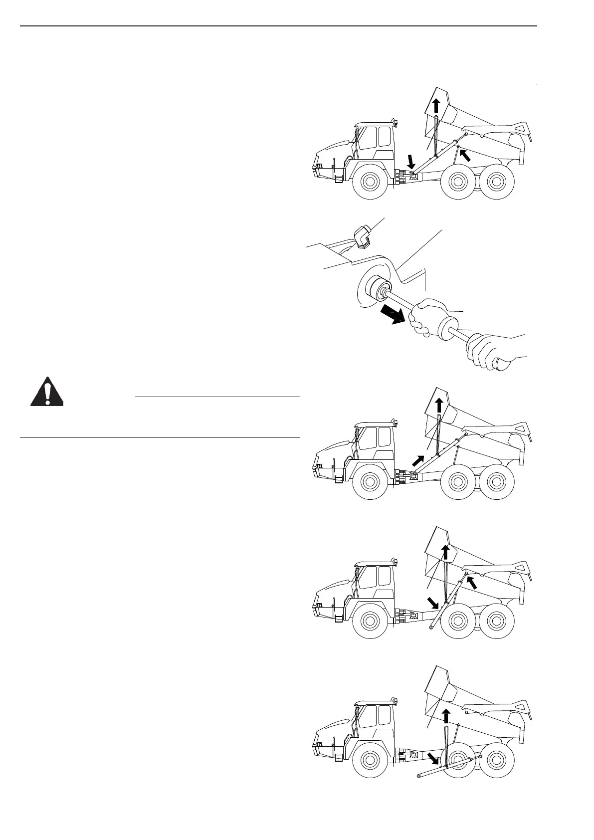
The Tilt Cylinders are located on the rear wagon on each
side of the dumper body.
To remove the cylinders, rise the dumper body, and place
body on safety stand.
Removal
Thoroughly clean the tilt cylinder and the area around for
any accumulated dirt.
Place a container below the cylinder to catch any hydrau-
lic fluid spilt during removal.
Mark each hydraulic line for proper location and plug lines
as they are disconnected from cylinder.
Fasten a lifting sling between the two hose clamps on
tilting cylinder.
Lift the cylinder slightly to remove the weight on the lower
pivot bolt.
To remove the upper pivot bolt, unscrew securing screws
and washers. Disconnect lubrication lines if fitted.
Remove the pivot bolt and expansion rings using a slide
hammer to withdraw the bolt. Slide hammer must be
equipped with a M20 adapter to fit the bolt.
When bolt is free, lower cylinder to get clear of bracket.
Remove lower pivot bolt as described for upper.
Be aware of the risk of injury to people and equipment
when handling heavy objects!
Carefully lift and push cylinder rearwards out of bracket,
and swing front end of cylinder out, then lower to ground
level.
If the cylinder is removed for exchange, unscrew the hose
fittings attached for possible reuse.
Installation
Check the condition of the connector seals, replace if
necessary. Apply a light coat of oil to the connector seals.
Install the connectors in cylinder body, and tighten.
Install cylinder in opposite order as described for removal.
Pivot bolts are installed with the lubrication supply bore
facing in, and lubrication cross bore pointing perpendicu-
larly to cylinder center line.
Pivot bolts are driven in using a soft mallet. Make sure
pivot bolts and attaching parts are centred before secur-
ing screws are tightened. Install lubrication lines. Recon-
nect hydraulic hoses.
Control
Check that all connections are located in the same posi-
tions as before removal, and that all hoses are correctly
routed.
Perform startup test procedure.
Ref. section: Startup test procedure.
WARNING
Figure 41