Engine
SHOP MANUAL
Ch 1 page 27
8. NOx sensor (T115)
There is a NOx sensor in the system. It is used to measure the content of nitrogen oxide compounds in the
exhaust gases after exhaust gas aftertreatment. This sensor reports to EEC3, which notifies EMS. The sensor
is electrically heated by EEC3. The NOx sensor is located on the SCR catalytic converter’s exhaust outlet.
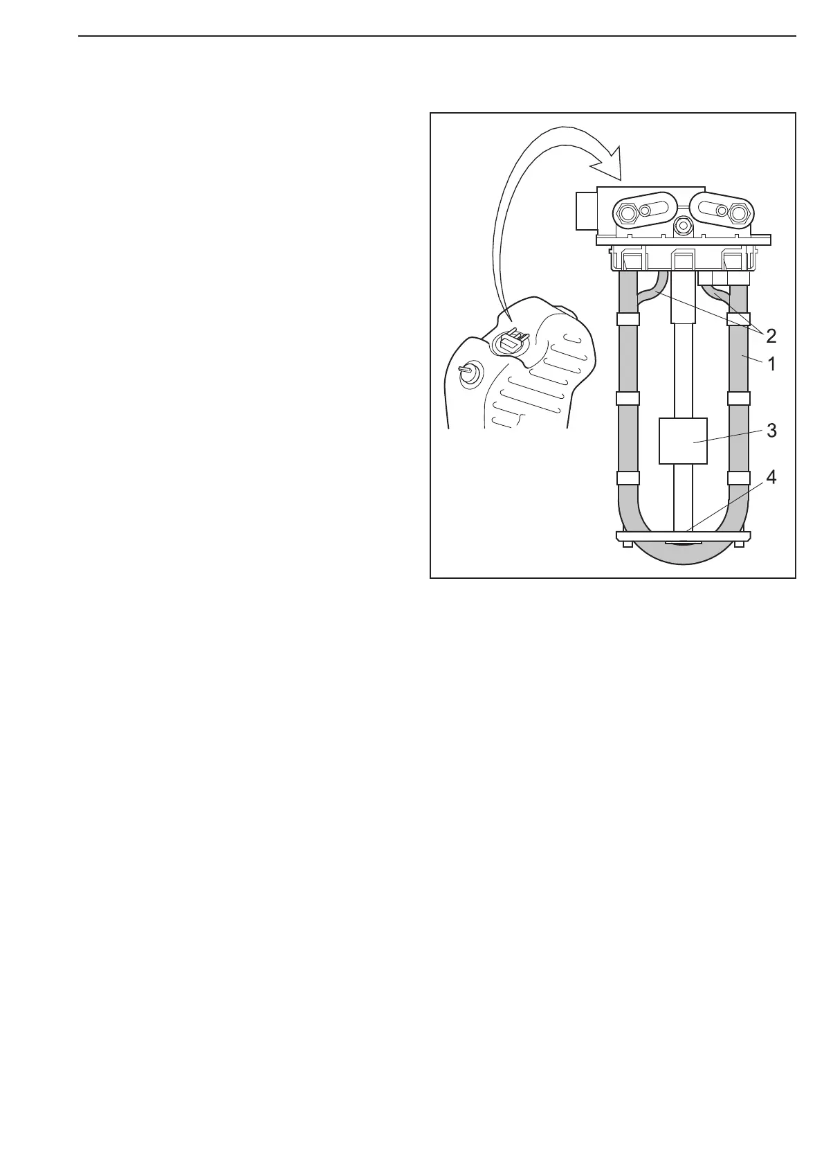
4. Level sensor and temperature sensor (T116)
There is a level and temperature sensor in the
reductant tank which measures the fluid level
and fluid temperature. This sensor reports to
EEC3. The sensor is located in the reductant
tank.
1 Pipe for coolant
2 Pipe for reductant
3 Level sensor
4 Temperature sensor
6. Reductant pump (V183)
To achieve the right reductant pressure prior to metering in the exhaust system, there is an electrically oper-
ated reductant pump with variable speed control in the system which is monitored and activated by EEC3. The
reductant pump reports pump speed to EEC3. The reductant pump is heated by the engine’s coolant at low out-
door temperatures. The reductant pump is located on the reductant tank bracket underneath the reductant tank.
7. Reductant doser EEC3 (V117)
To ensure that the correct quantity of reductant is metered to the exhaust gases, there is an electrically oper-
ated reductant doser in the system which is monitored and activated by EEC3. The reductant doser reports the
pressure and temperature of the reductant to EEC3. The reductant doser is electrically heated and located on
the hydrolysis catalytic converter.
5. Electrically heated reductant hoses (H25, H26, H27 and H28)
The hoses designed for reductant are electrically heated in order to prevent ice formation at low outdoor tem-
peratures. Electrical heating of the hoses is activated by EEC3. The hoses run between the connections on the
reductant pump and to the reductant doser and then to the reductant tank.
Figure 40