SHOP MANUALSHOP MANUAL
FRONT WAGON
Ch 7 Page 46 Ch 7 Page 47
FRONT WAGON
Cab
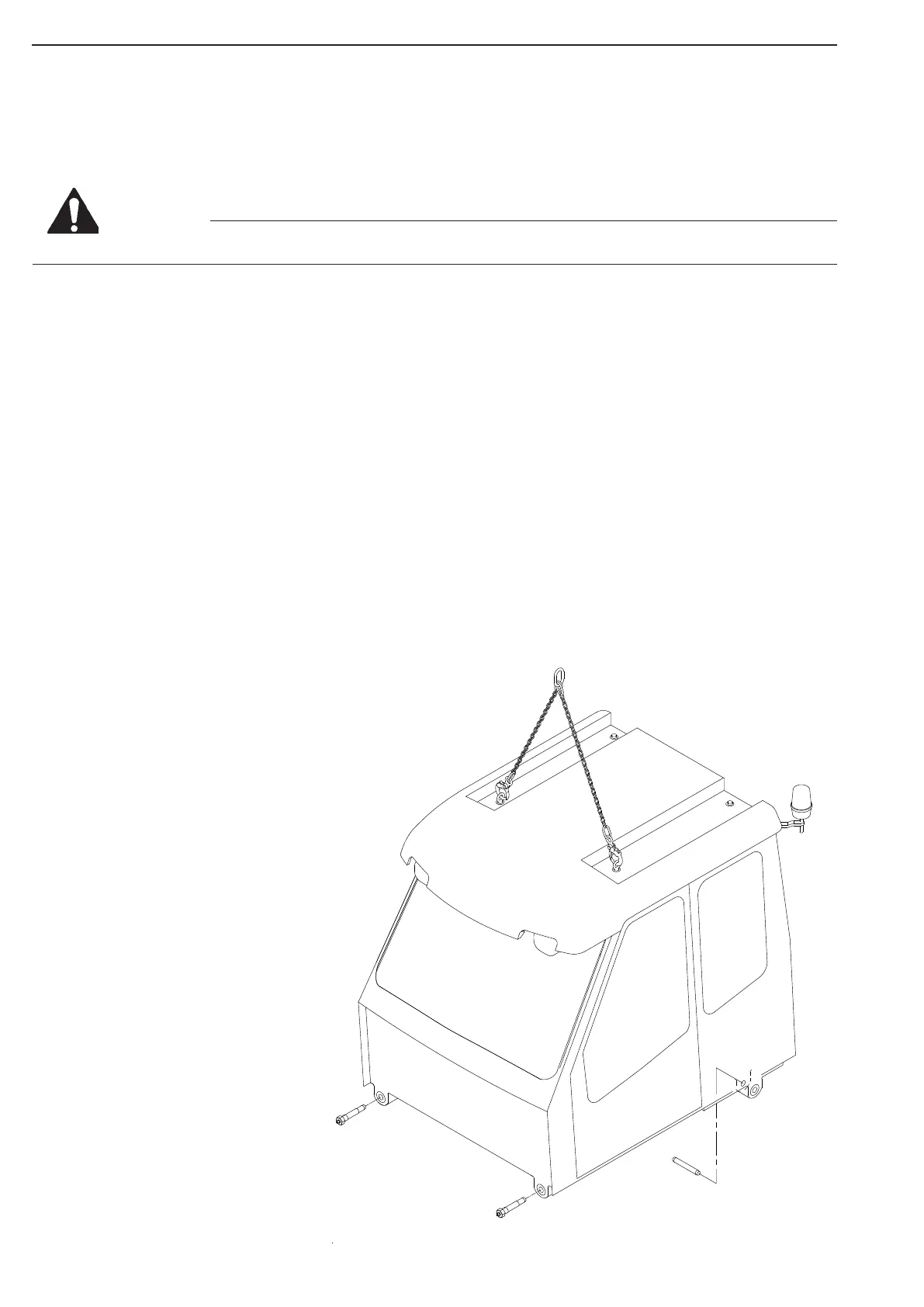
Lifting
Device
Cab Mount-
ing/Hinge
Bolts, Rear
Cab Mount-
ing Bolts,
Front
Remove the locking rings and drive the hinge bolts inwards to free the cab from the front frame. Retrieve the
bolts.
Lift the cab off the dumper, and place on woodblocks, resting on the mounting brackets.
Be aware of the risk of injury to people and equipment when handling heavy objects!
Check the cab bolt rubber bushings for wear, and replace if necessary.
If the cab is going to be replaced with another unit, parts have to be moved over until the new cab has the same
configuration as the one removed.
The amount is determined by the configuration of the new cab supplied.
Installation
Lift the cab onto the dumper, using the crane, and position the cab to enter the two rear mounting/hinge bolts.
Drive the bolts in position from inside.
Replace the locking rings.
Tilt the cab, by means of the crane, high enough to place on safety stand.
Replace the hydraulic tilting cylinder in the cab bracket, if fitted, by installing the bolt and nut.
Tilt the cab fully.
Apply tilt support. Tilt support is located in front fender RHS
Hook the two springs, holding the hose support, back into position.
Replace hoses and cables in opposite order of what described for removal.
Replace the cover plates under the cab.
Lower the cab to normal position, and install the front cab bolts. Torque: 277Nm
Replace the electrical connections on the left hand side of the electrical central.
Replace ground connections.
Refill AC system.(Authorized personnel only)
Refill engine coolant. (For fluid type and specifications, refer to the DOOSAN Operating & Maintenance Manual
Chapter 6)
Control
Check that all parts are located as before removal.
Turn the main battery switch on, and check the
function of electrical components affected.
Start the engine and check that the
hydraulic system is functioning properly.
Bleed the brake circuits.
Perform a test drive.
WARNING
Figure 104