BRI-BD/LGATE-BD (ISDN-BRI Line Circuit Pack)
Issue 4 May 2002
10-259 555-233-123
BRI-BD/LGATE-BD (ISDN-BRI Line
Circuit Pack)
NOTE:
Some of the information in this section is reserved for future use.
!
CAUTION:
A detailed flowchart for isolating and resolving Packet Bus faults is included
in Chapter 9, “Packet Bus Fault Isolation and Correction”. This flowchart,
along with the other information presented in the chapter, can help in
resolving problems that involve more than a single station or circuit pack.
Whenever the repair procedures for this Maintenance Object refer to Packet
Bus and/or Packet Control maintenance, be sure to reference Chapter 9,
“Packet Bus Fault Isolation and Correction”, in addition to the relevant MO
documentation.
ISDN-BRI Line is a packet port circuit pack that provides access to ISDN-BRI
endpoints. The ISDN-BRI Line circuit pack supports 12 ports, each of which
provides access to ISDN stations. Voice and circuit-switched data from the ISDN
stations are carried on the Time Division Multiplex (TDM) Bus. Signaling is carried
over the Packet Bus.
LEDS
The ISDN-BRI Line circuit pack performs extensive initialization tests and lights
both the red and green LEDS during the initialization testing. See Chapter 7, “LED
Interpretation”, for more details on circuit pack status LEDs.
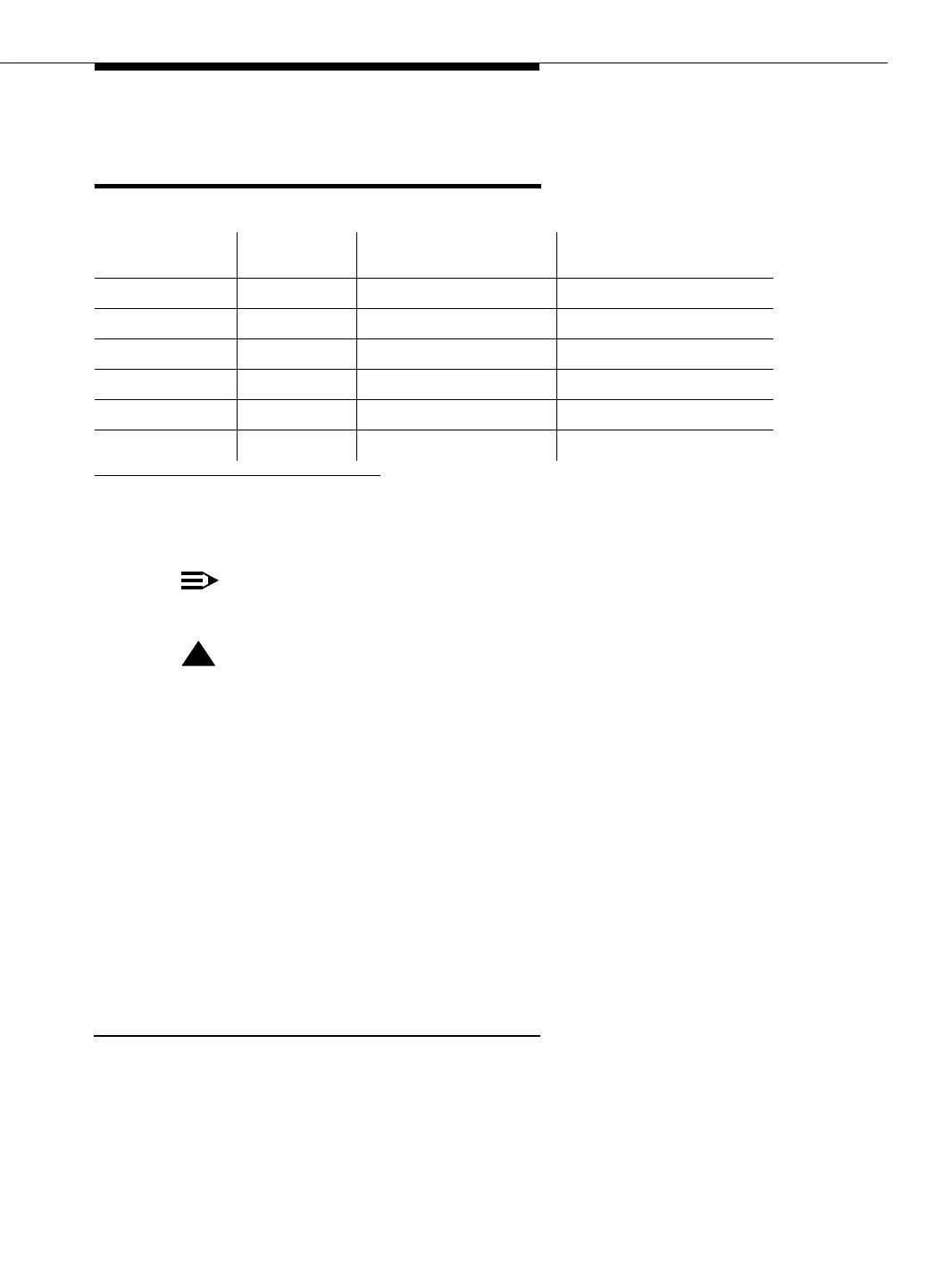
MO Name (in
Alarm Log) Alarm Level
Initial Command to
Run
1
1 Where P is the port network number (1 for PPN and 2 or 3 for EPN); C is the carrier
designation (A, B, C, D, or E); and SS is the address of the slot in the carrier where the circuit
pack is located (01, 02, etc.).
Full Name of MO
BRI-BD MAJOR test board PCSS l ISDN-BRI Line Circuit Pack
BRI-BD MINOR test board PCSS l ISDN-BRI Line Circuit Pack
BRI-BD WARNING test board PCSS sh ISDN-BRI Line Circuit Pack
LGATE-BD MAJOR test board PCSS l DEFINITY Lan Gateway
LGATE-BD MINOR test board PCSS l DEFINITY Lan Gateway
LGATE-BD WARNING test board PCSS sh DEFINITY Lan Gateway