LED Interpretation
555-233-123
7-4 Issue 4 May 2002
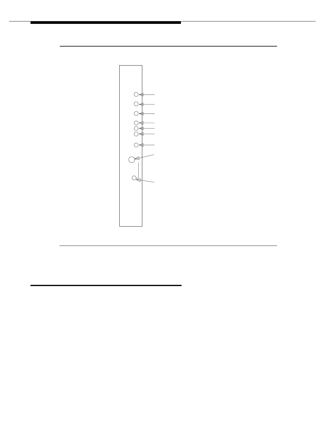
Figure 7-1. Indicators on Maintenance and Processor Circuit Packs
Duplication Interface circuit pack
LEDs
In a High or Critical Reliability system, there are two Duplication Interface circuit
packs. One is located in carrier A and one in carrier B of the PPN. Each circuit
pack has two groups of LEDs. The top three have the traditional function of
indicating the status of the pack. The LED located at the bottom of the faceplate
directly beneath the SPE AUTO switch is labeled OVERRIDE. Under normal
operating conditions, the SPE AUTO switch is in the AUTO (center) position (see
Figure 7-2 on page 7-5). This means that the system controls which SPE is active.
However, there will be times (during maintenance activity, for example) when you,
the technician, may choose to manually override the SPE selection function. To
override system selection of the Active processor, move the SPE Select switches
one at a time on both Duplication Interface circuit packs from the AUTO position to
either the “A” position or the “B” position. Thus, when both SPE Select switches
have been moved to either “A” or “B,” the OVERRIDE LED turns red and lights
steadily.
ALARM LED (RED)
TEST LED (GREEN)
BUSY LED (AMBER)
MAJOR ALARM LED (RED)
MINOR ALARM LED (RED)
WARNING ALARM LED (AMBER)
ACKNOWLEDGEMENT LED (GREEN)
CONTROL SWITCH
EMERGENCY TRANSFER
ALARMS
MAJOR
MINOR
WRNG
ACK
EMERGENCY
TRANSFER
OFF ON
AUTO
EMERGENCY TRANSFER LED (RED)