Reliability Systems: A Maintenance Aid
555-233-123
6-20 Issue 4 May 2002
Each Duplication Interface circuit pack has another red LED associated
with the SPE Select Switch. The purpose of the red switch LED is to serve
as a reminder that an SPE is being forced to be the Active SPE and,
therefore, the system is not duplicated. Both SPE Select Switch LEDs (one
on each Duplication Interface circuit pack) are on when an SPE is being
forced to be the Active SPE by the consistent positions of the two SPE
Select Switches. Both LEDs are extinguished when the SPE Select Switch
positions are inconsistent or when both SPE Select Switches are in the
position. In the latter two cases, the Active SPE is automatically selected
by the system software.
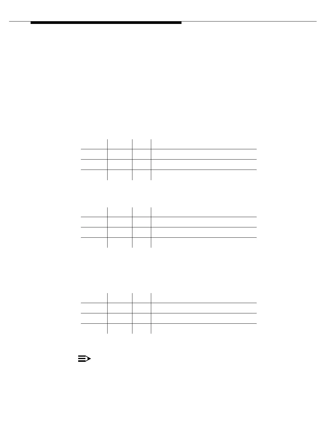
■ Processor Interface Circuit Pack (TN765):
■ Network Control Circuit Pack (TN777B):
There is also an yellow LED (below Memory Card slot). When ON, the
Memory Card is in use.
■ Packet Control Circuit Pack (PCCP) (TN778)
■ Tone-Clock Circuit Pack:
NOTE:
For information on the standard amber/green/red LEDs see
TONE-BD Maintenance Object in Chapter 10, ‘‘Maintenance Object
Repair Procedures’’.
Yellow Green Red Meaning
On - - Link terminated at PICP
On - Maintenance running on PICP
- - On Fault on PICP
Yellow Green Red Meaning
On - - Link terminated at NCCP
On - Maintenance running on NCCP
- - On Fault on NCCP
Yellow Green Red Meaning
On - - Link terminated at PCCP
On - Maintenance running on PCCP
- - On Fault on PCCP
 Loading...


