Packet Bus Fault Correction
Issue 4 May 2002
9-33 555-233-123
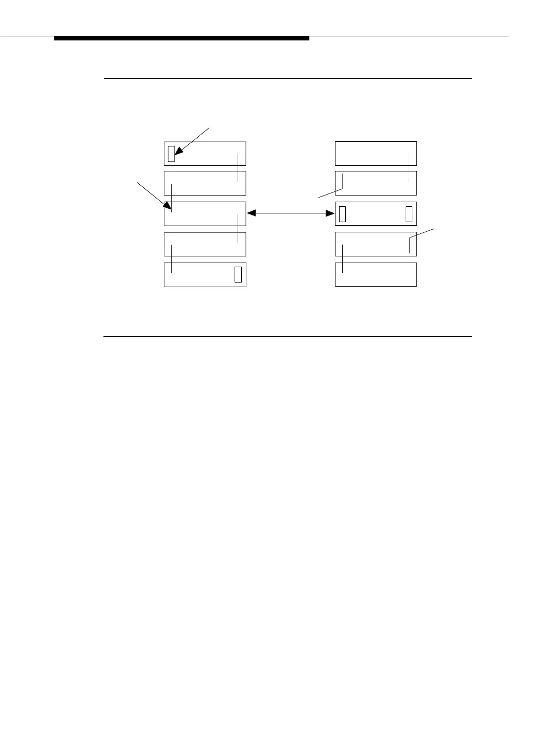
Figure 9-7. Carrier Rewiring Example
Procedure 4 is organized into two parts, as follows:
Part 1:
1. Power down the PN. See ‘‘Removing Power’’ section in Chapter 5,
‘‘Routine Maintenance Procedures’’.
2. Replace all of the TDM/LAN cables and both TDM/LAN terminators.
3. Restore power to the PN. See ‘‘Restoring Power’’ section in Chapter 5,
‘‘Routine Maintenance Procedures’’.
4. Determine if the packet bus fault is still present.
5. If the fault is present, go to Part 2.
Part 2:
Processor Port Network:
1. Terminate the Packet Bus so that it extends only from the Active control
carrier (that is, the carrier that contains the Active SPE) to the carrier that
contains the Maintenance/Test circuit pack. To allow this procedure to
isolate the failure to the smallest possible number of carriers, place the
Maintenance/Test circuit pack into a carrier that contains a processor
complex, if possible.
Terminator
TDM/LAN
Cable
Normal Cabinet
(Rear View)
Control Carrier
Modified Cabinet
(Rear View)