SHOP MANUAL
DRIVE LINE
Ch 3 page 40 Ch 3 page 41
DRIVE LINE
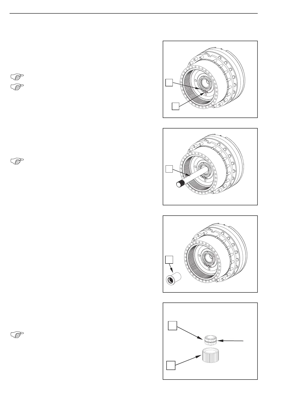
1
2
1
1
1
2
Install the lock plate (1) and fasten it by means of
locking bolts (2).
Tightening torque ........................................ MA = 86 Nm
Always use new locking bolts!
Prior to install the locking bolts, the leakage test of the
brake chamber/wheel head (see 1.2.5) and of the brake
hydraulics (see 1.2.6) can already be carried out!
Insert the stub shaft (1) into the differential until contact.
Left and right stub shaft are of a different length!
Mount the driver (1) until contact is obtained.
Press roller bearing (1) into planetary gear (2) until the
circlip (see arrow) has snapped into the recess of the planetary
gear.
Roller bearing and planetary gear are damaged at the
disassembly!
Figure 108
Figure 107
Figure 106
Figure 105