SHOP MANUAL
DRIVE LINE
Ch 3 page 90 Ch 3 page 91
DRIVE LINE
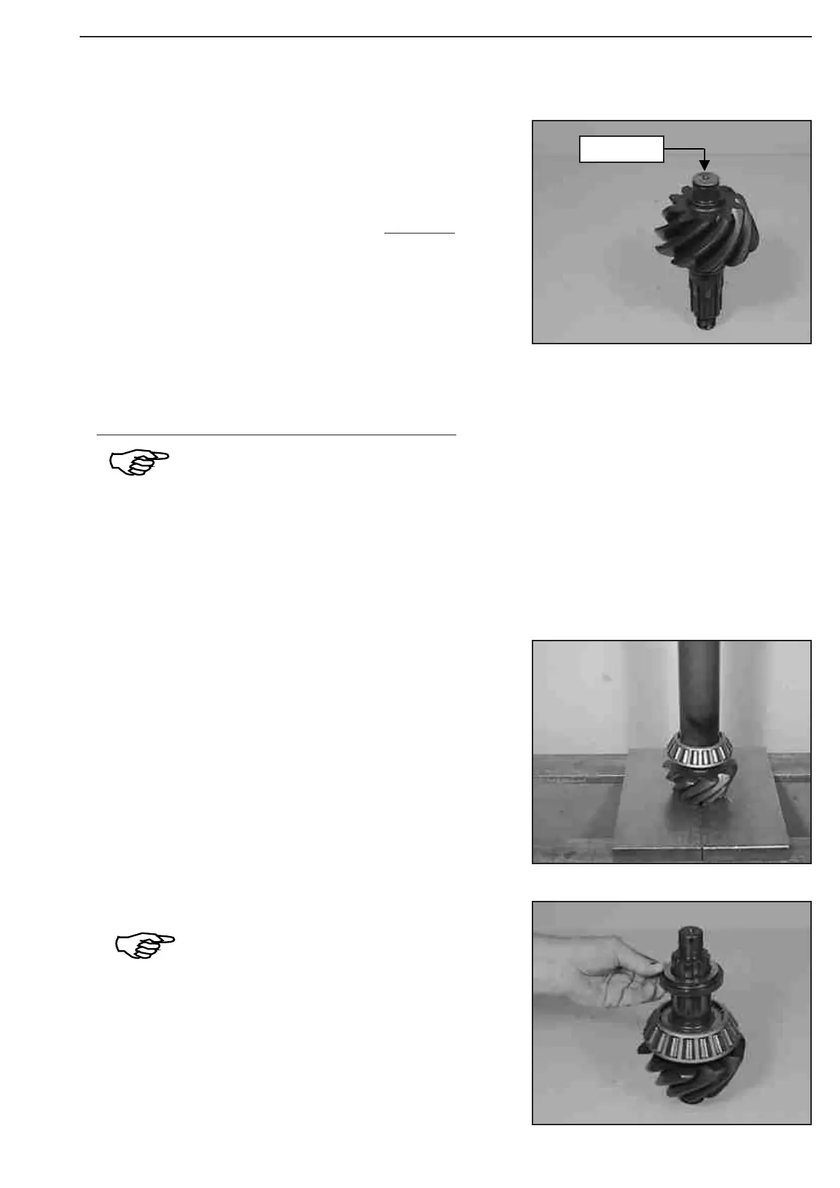
Read Dimension d (pinion dimension).
Dimension d e.g. (197 + 0,1 mm) ............... 197,10 mm
Example „A2„:
Dimension c (Figure 245)................................. 53,60 mm
Dimension d ....................................... + 197,10 mm
gives Dimension Y (install. Dimension) 250,70 mm
Adjust Torque of Drive pinion bearing 1 ... 2 Nm (without shaft
seal), see Figure 248 ... 254 !
We know from experience that at application of the
adjusting ring (e.g. s = 15,28 mm) found at the
disassembly, the required torque is obtained !
However, the later checking of the torque
is necessary !
Line up the adjusting ring e.g. s = 15,28 mm, with the small collar
showing upward.
Press bearing inner race over the drive pinion stem until contact is
obtained.
Example „A3„:
Dimension Y ............................................. 250,70 mm
Dimension X ............................................. - 250,10 mm
gives Shim e.g. s = 0,60 mm
The assembly of the shim is realized at Figure 258 !
197
+0,1
Figure 248
Figure 247
Figure 246