SHOP MANUAL
DRIVE LINE
Ch 3 page 162 Ch 3 page 163
DRIVE LINE
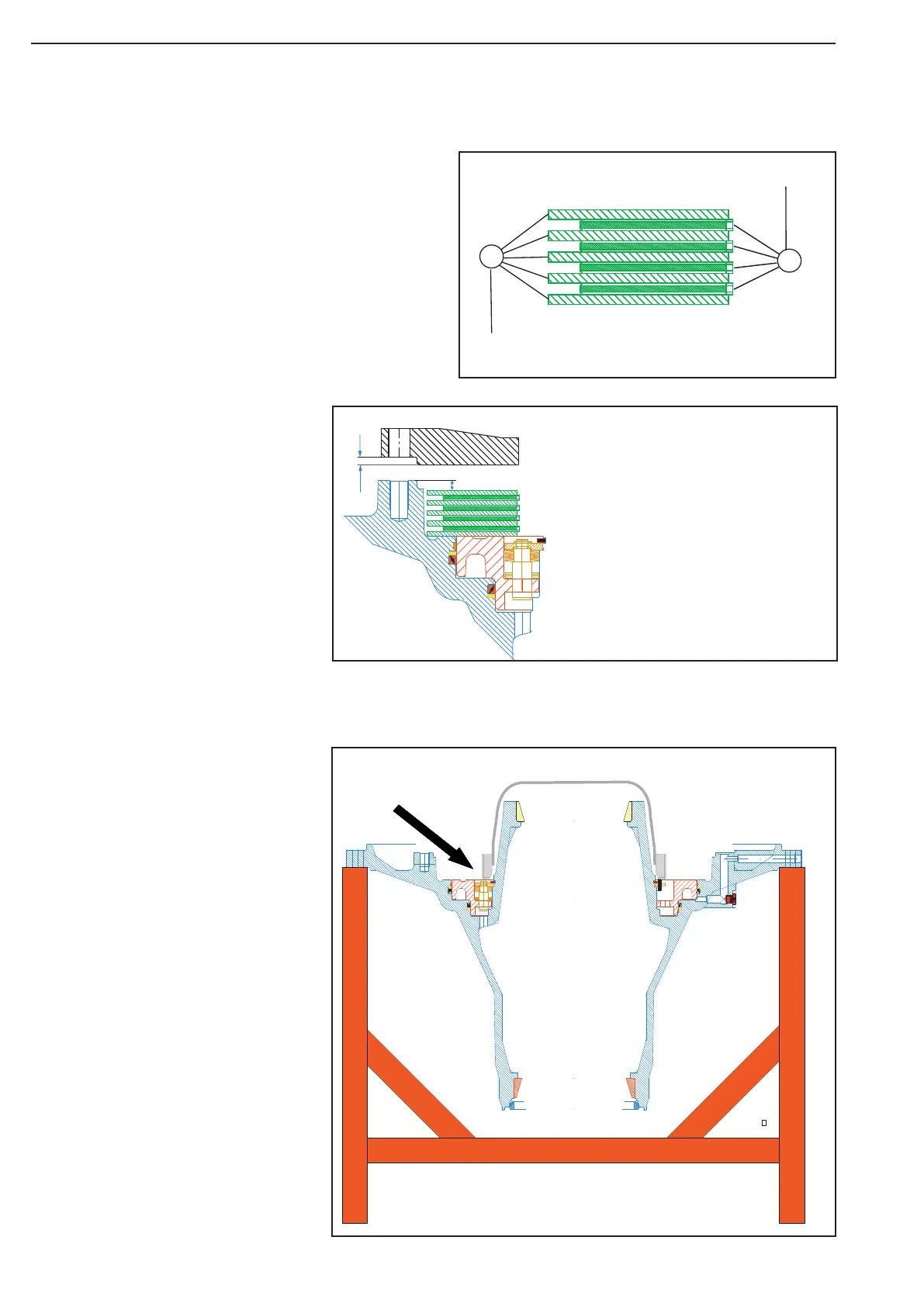
Calculation example:
Measure x.................................. 8,00
Measure Y.................................. - 6,50
Clearance.................................. = 1,50
Clearance:
Min: 1,3+0,3 mm (New discs)
Max: 4,3 mm (Used discs)
Y
X
Brake disc- stationary (Qty 5)
Available3,8 mm, 4,0 mm, or 4,2 mm.
Brake disc- rotating (Qty 4)
Available 4,7 mm
Discs unit
1
2
Assembly the disc package in
the hub housing.
See the calculation example
below
Prepare stand for the hub work over
Clean the bearing surface and
assemble the bearing cup
Clean the surface and
assemble the seal ring
Be careful with the seal ring
Insert the plug
Assemble the guide ring
Pos 23-24
Assemble the piston ring
Pos 21 - 22
Assemble the guide ring
Use glue: Loctite no.406
at both ends.
Assemble 6 pcs. of the slot pin
into the return mechanism
Slot pin 6x20 DIN 1481
Place the "line up tool"
part No. 514663
Before placing of the discs, place the
tool, Spline mandre to the hub.
Tool, part No. 519429
Figure 488
Figure 487
Figure 489